LG RM-15LA70 Service Manual
LG RM-15LA70 Manual
 |
View all LG RM-15LA70 manuals
Add to My Manuals
Save this manual to your list of manuals |
LG RM-15LA70 manual content summary:
- LG RM-15LA70 | Service Manual - Page 1
biz.LGservice.com e-mail:http://www.LGEservice.com/techsup.html LCD TV SERVICE MANUAL CHASSIS : ML-041B MODEL: RT-15LA70(RT-15LA70 Rev A) *( ) ID LABEL Model No. CAUTION BEFORE SERVICING THE CHASSIS, READ THE SAFETY PRECAUTIONS IN THIS MANUAL. R *Same looking with new chassis *Issue Date; 2004. 06 - LG RM-15LA70 | Service Manual - Page 2
CONTENTS CONTENTS 2 PRODUCT SAFETY 3 SPECIFICATION 4 TIMING CHART 11 ADJUSTMENT INSTRUCTION 12 TROUBLE SHOOTING 16 BLOCK DIAGRAM 21 WIRING DIAGRAM 23 EXPLODED VIEW 24 EXPLODED VIEW PARTS LIST 25 REPLACEMENT PARTS LIST 26 SVC. SHEET - LG RM-15LA70 | Service Manual - Page 3
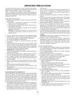
recommended in this manual to prevent servicing of a receiver whose chassis is not isolated from the AC power line. Use a transformer of adequate power this TV receiver is the High Voltage Section and the LCD PANEL Figure) Plug the AC cord directly into the AC exceed 0.75 volt RMS which is corresponds - LG RM-15LA70 | Service Manual - Page 4
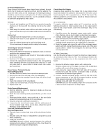
: Safety First. General Servicing Precautions 1. Always unplug the receiver AC power cord from the AC power source before; a. Removing receiver or any of its assemblies. 4. Unless specified otherwise in this service manual, clean electrical contacts only by applying the following mixture to the - LG RM-15LA70 | Service Manual - Page 5
leads extending from the circuit board and crimp the "U" with long nose pliers to insure metal to metal contact then solder each connection. Power Output, Transistor Device Removal/Replacement 1. Heat and remove all solder from around the transistor leads. 2. Remove the heat sink mounting screw (if - LG RM-15LA70 | Service Manual - Page 6
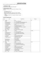
specification is applied to ML-041B chassis. 2. Requirement for Test Testing for standard of each part must be followed in below condition. (1) Temperature: 25°C ± 2°C (2) Humidity: 65% ± 10% (3) Power Mode Back light Unit R/T Typ. Specification LPL TFT Color LCD Module 15.0 inches(380.16mm) - LG RM-15LA70 | Service Manual - Page 7
AV Input 4 S-Vedio Input 5 Component input 6 PERI TV Connector 7 RGB(VGA)Input 8 H/p input 9 PC Sound Progressive Scan 21 Motion Detection 22 SRS WOW 23 wivel Speaker 24 Ez-pip 25 ARC 26 DRP 27 DCDI 28 HDCP Specification TOP, FLOF,LIST 10 page NEC Code 2 1 1 Full SCART : 1 1 1 1 YES NO BG, DK BG, - LG RM-15LA70 | Service Manual - Page 8
Specification 6-1.General Specification(TV) No. Item 1 Video input applicable system 2 Receivable broadcasting system 3 RF input channel 4 Input voltage 5 Tuning system 6 Operting environment 7 Storage environment Specification ) 7)NTSC Area(RM) PAL FRANCE NTSC JAPAN PAL, 200PR.(Option) NTSC - LG RM-15LA70 | Service Manual - Page 9
1 Power Supply Normal Stand By Suspend Mode DPM Off Mode Cut-off Switch off ITEM 2 D-SUB Pin Configuraion 3 Control Function Specification H/V , 525p, 750p, 1125i) 6-2.Power NO Item 1 AC Power Shut Down Voltage 2 DC Voltage, Inverter 3 DC Voltage, LCD Panel 4 DC Voltage, Audio - LG RM-15LA70 | Service Manual - Page 10
6-3. Power NO Item 1. Video Input Level 2. Audio Input Level 3. Audio Input Frequency Response 4. Audio Min Typ Max Unit -85 dBm 0.1 10 m 0.1 9 m -70 dBm -70 dBm Remark LGE Specification 30 degree NTSC ONLY [Table 7] Timming chart of Receivable Mode * H [dot] / V [line] Mode - LG RM-15LA70 | Service Manual - Page 11
VIDEO SYNC TIMING CHART D C A E B > Mode 1 2 3 4 5 6 7 H/V Sync Dot Sort Polarity Clock Frequency Total Period Video Active Time (E) (A) H+ 31.468 800 640 25.175 - LG RM-15LA70 | Service Manual - Page 12
instruction is for the application to the LCD TV. 2. Adjustment 2.1 Adjustment overview The unit is set to automatically adjust using the factory automation equipment. However when errors occur, it should be adjusted manually mode using the adjustment (SVC) remote controller, and press VOL+ Key - LG RM-15LA70 | Service Manual - Page 13
*Option(PAL) NO ITEM 1 Side AV 2 SCART 3 PC 4 SideComp 5 16:9 6 200PR 7 Text 8 ACMS 1 HiDev 2 Hotel 3 Top 4 I II SAVE 5 Turbo Vol 6 Ch/Aus CONDITION Option 1 1 1 1 1 1 0 1 1 Option 2 0 0 1 1 0 0 REMARK 0: Side AV Off 1: Side AV On 0: SCART Off 1: SCART On 0: PC Off 1: PC On 0: SideComp Off 1: - LG RM-15LA70 | Service Manual - Page 14
Manual Operating System: MS Windows 98, 2000, XP Port Setup: Windows 98 => Don't need setup Windows 2000, XP => Need to Port Setup. This program is available to LCD ST POWER IBM Compatible PC 15 10 5 PARALLEL PORT OFF ON 5V F Power inlet (required) 220 Power Select Switch (110V/220V) Power LED - LG RM-15LA70 | Service Manual - Page 15
SVC REMOCON 1 POWER To turn the TV on or off 2 POWER ON To turn the TV on automatically if the power is supplied to the TV. (Use the POWER key to deactivate): It should be deactivated when delivered. 3 MUTE 4 P-CHECK 5 S-CHECK 6 ARC To activate the mute function. To check TV screen image - LG RM-15LA70 | Service Manual - Page 16
TROUBLESHOOTING No power (LED indicator off) :[A]Process Check 15V or 5V of Lips Check short of main B/D Fail or Change Lips Pass Check Output of IC1107, IC104 Pass - LG RM-15LA70 | Service Manual - Page 17
No Raster :[B]Process Check LED Status on display unit Fail Repeat A PROCESS Check L900,L901 L902,L903 Fail Pass Check the input/ Output of IC901 Fail Pass Check inverter Connector or inverter Fail Pass Check panel link Cable or module Fail Pass Check input source cable and jack - LG RM-15LA70 | Service Manual - Page 18
No Raster on Component signal Repeat [A] Process Pass Check the signal of L1200, L1202, L1203 Fail Pass Check the input/ output of IC1 Fail Check the input/output of IC800, IC851 Fail Pass Check the input/ output of IC901 Fail Pass Check input source cable and jack Check JA1200 or - LG RM-15LA70 | Service Manual - Page 19
No Raster on AV Signal (Video, S-Video) No Raster on TV(RF) signal Repeat [A] Process Pass Check the output of Fail TU1000 Check 5V, 33V of TU1000 Re-soldering or Fail Change the defect part Check - LG RM-15LA70 | Service Manual - Page 20
No Sound Check the input source Pass Change source input Fail Re-soldering or Check the input/output Change the defect part of IC1 Fail Check X11 Pass Check the input/output Re-soldering or of IC100,IC101 Fail Change the defect part Pass Check the speaker Pass Check the speaker wire - LG RM-15LA70 | Service Manual - Page 21
BLOCK DIAGRAM ML-041B Block Diagram ANALOG SIGNAL DIGITAL SIGNAL SOUND INPUT IF +,- INPUT SOUND OUTPUT POWER SIDE_AV IC100 IC101 Audio Amp L, R TC90A65F IC500 SM5301BS IC800 GM2221 IC901 TTL 1 OUT TTL 2 OUT LVDS1 OUT AT49F IC905 AT24C16 IC4 RGB OUT VCTI IC1 - LG RM-15LA70 | Service Manual - Page 22
generate the 33V used for the tuner. 15V power is directly used by the sound amplifier IC and is also used to generate 5V power through the regulator. 12V power is used for the LCD panel power, and 5V power is converted to 3.3V and 1.8V power through the regulator, which in turn supplies electrical - LG RM-15LA70 | Service Manual - Page 23
WIRING DIAGRAM 11P_2.0MM H-H 100MM 3 1 1. 20P LVDS : 200MM 2. 41P TTL 3. 50P TTL : 145MM 2 4P_2.0MM H-B (17LZ50 ONLY) 6P_2.0MM H-B 600MM 6 2P_AC_SOCKET SPEAKER 18P_1.0MM FFC 54MM (RZ ONLY) 7 18P_1.0MM FFC 54MM 8 4P_2.5MM SHIELD GND: 2PIN, 4PIN 500MM 750MM RECEPTERCLE 9 SIDE AV (17LZ50 - LG RM-15LA70 | Service Manual - Page 24
5 1 EXPLODED VIEW 12 3 16 10 2 9 13 14 11 8 15 19 17 18 20 4 5 6 7 22 21 - LG RM-15LA70 | Service Manual - Page 25
CABINET ASSEMBLY RZ-15LA70 NON ML024E . LCD(LIQUID CRYSTAL DISPLAY), LC150X02-A4 LG PHILPS TFT COLOR TN RM-15LA70 ML-041B SUB TOTAL BRAND IR BOARD ASSY METAL ASSEMBLY, FRAME MAIN 15LA66/70 (LPL MODULE ONLY) MAIN TOTAL ASSEMBLY, RT-15LA70(LPL) BRAND ML-041B PWB(PCB) ASSEMBLY, POWER, RZ-15LA70 POWER - LG RM-15LA70 | Service Manual - Page 26
2012 R/TP C928 0CH3104K946 100000PF 50V Z F 2012 R/TP C929 0CH3104K946 100000PF 50V Z F 2012 R/TP *S *AL LOC. NO. PART NO. DATE: 2004. 06. 03. DESCRIPTION / SPECIFICATION C930 C934 C935 C936 C937 C938 C939 C940 C943 C944 C945 C946 C947 C948 C949 C950 C956 C964 C965 C967 C968 C970 C13 C14 C2 - LG RM-15LA70 | Service Manual - Page 27
PART NO. DATE: 2004. 06. 03. DESCRIPTION / SPECIFICATION C118 C12 C125 C126 C200 C22 C23 C24 C25 C26 C27 50V 5% R/TP NP0 *S *AL LOC. NO. PART NO. DATE: 2004. 06. 03. DESCRIPTION / SPECIFICATION C57 C58 C74 C83 C85 C86 C88 C89 C108 C1102 C1103 C1105 C1106 C1109 C111 C1118 C112 C1124 C1130 C1132 - LG RM-15LA70 | Service Manual - Page 28
ATMEL 8P AT24C16AN-10SI-2.7 ATMEL 8P MP7720 MONOLITHIC POWER SYST MP7720 MONOLITHIC POWER SYST "M52758FP MITSUBISHI 36PIN, R" "MC14066BDR2 14P,SOIC *AL LOC. NO. PART NO. DATE: 2004. 06. 03. DESCRIPTION / SPECIFICATION L2 0LC1032101A 10UH 10% 3216 R/TC FI-C3216- L8 0LC1032101A 10UH 10% 3216 - LG RM-15LA70 | Service Manual - Page 29
. PART NO. DATE: 2004. 06. 03. DESCRIPTION / SPECIFICATION R57 R59 R6 R817 R818 R9 R903 R908 R910 R915 R934 OHM 1/10 W 5% 1608 R/TP *S *AL LOC. NO. PART NO. DATE: 2004. 06. 03. DESCRIPTION / SPECIFICATION R23 R230 R24 R240 R25 R28 R29 R3 R34 R37 R4 R41 R45 R46 R49 R5 R50 R51 R52 R53 R54 R55 R56 - LG RM-15LA70 | Service Manual - Page 30
LG C&D N TACT 2LEAD 100G(TA) LG C&D N TACT 2LEAD 100G(TA) LG C&D N TACT 2LEAD 100G(TA) LG C&D N TACT 2LEAD 100G(TA) LG C&D N TACT 2LEAD 100G(TA) LG C&D N TACT 2LEAD 100G(TA) LG C&D N TACT 2LEAD 100G(TA) LG DATE: 2004. 06. 03. DESCRIPTION / SPECIFICATION LED2100 0DL200000CA SAM5670(DL-2LRG) BK Y- - LG RM-15LA70 | Service Manual - Page 31
- LG RM-15LA70 | Service Manual - Page 32
- LG RM-15LA70 | Service Manual - Page 33
P/NO : 3828TSL103G Jun., 2004 Printed in Korea
-
 1
1 -
 2
2 -
 3
3 -
 4
4 -
 5
5 -
 6
6 -
 7
7 -
8
-
9
-
10
-
11
-
12
-
13
-
14
-
15
-
16
-
17
-
18
-
19
-
20
-
21
-
22
-
23
-
24
-
25
-
26
-
27
-
28
-
29
-
30
-
31
-
32
-
33
 |
 |

R
LCD TV
SERVICE MANUAL
CAUTION
BEFORE SERVICING THE CHASSIS,
READ THE SAFETY PRECAUTIONS IN THIS MANUAL.
CHASSIS : ML-041B
MODEL: RT-15LA70
(RT-15LA70 Rev A)
website:http://biz.LGservice.com
*(
) ID LABEL Model No.
*Same looking with new chassis
*Issue Date; 2004. 06