LG RM-15LA70 Service Manual - Page 14
Edid Adjustment
 |
View all LG RM-15LA70 manuals
Add to My Manuals
Save this manual to your list of manuals |
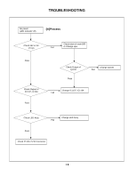
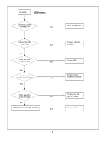
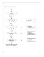
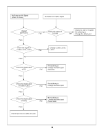
Page 14 highlights
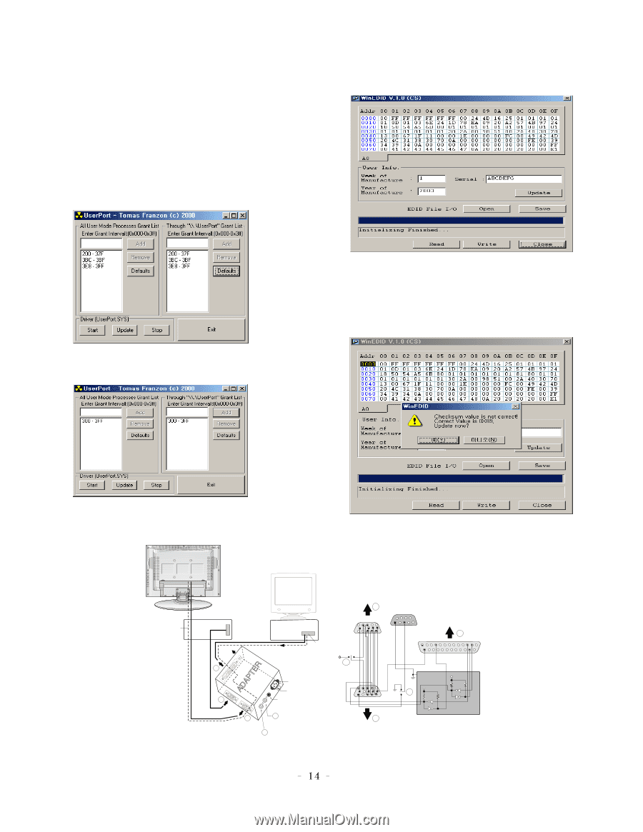
EDID ADJUSTMENT Windows EDID V1.0 User Manual Operating System: MS Windows 98, 2000, XP Port Setup: Windows 98 => Don't need setup Windows 2000, XP => Need to Port Setup. This program is available to LCD Monitor only. 2. EDID Read & Write 1) Run WinEDID.exe 1. Port Setup a) Copy "UserPort.sys" file to "c:\WINNT\system32\drivers" folder b) Run Userport.exe c) Remove all default number d) Add 300-3FF 2) Edit Week of Manufacture, Year of Manufacture, Serial Number a) Input User Info Data b) Click "Update" button c) Click " Write" button e) Click Start button. f) Click Exit button. Video Signal Generator Control Line PARALLEL Not used RS232C C VGS A MONITOR B V-SYNC ST POWER IBM Compatible PC 15 10 5 PARALLEL PORT OFF ON 5V F Power inlet (required) 220 Power Select Switch (110V/220V) Power LED E ST Switch A 9 11 5 6 1 6 1 13 25 C 1 14 ON E OFF 5V 4.7K 5V 4.7K 4.7K 74LS06 74LS06 B F V-Sync On/Off Switch (Switch must be ON.) Figure 1. Cable Connection
-
 1
1 -
2
-
3
-
4
-
5
-
6
-
7
-
8
-
 9
9 -
 10
10 -
 11
11 -
 12
12 -
 13
13 -
 14
14 -
 15
15 -
 16
16 -
 17
17 -
 18
18 -
 19
19 -
20
-
21
-
22
-
23
-
24
-
25
-
26
-
27
-
28
-
29
-
30
-
31
-
32
-
33
 |
 |