LG RM-15LA70 Service Manual - Page 22
Block Diagram Description
 |
View all LG RM-15LA70 manuals
Add to My Manuals
Save this manual to your list of manuals |
Page 22 highlights
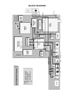
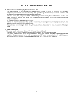
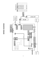
BLOCK DIAGRAM DESCRIPTION 1. Video Controller Unit & Display Data Conversion Unit The video controller unit receives the video signals inputted through the tuner, AV port (AV1, AV2, S-Video, component), and converts them into an analog RGB signal through the microcomputer (VCTI) combined with the video decoder that integrates various functions in one chip. Either the analog RGB, component YPbPr or PC RGB signal is selected by the switching IC and inputted to a scaler (GM2221), which is sent to the LCD module after being modified to an LVDS signal through the integrated LVDS IC. Or, it is sent to the LCD module as a TTL output. VCTi is the main microprocessor that handles video signal processing and sound signal processing. It also manages the RF signals received from the tuner. The scaler can control timing to fit into the LCD panel, and can also control the size and position of the input signal. 2. Power Supply Unit The power supply unit provides 15V and 5V DC power to the mainboard. The PWM Step-Up DC/DC Converter circuit is used to generate the 33V used for the tuner. 15V power is directly used by the sound amplifier IC and is also used to generate 5V power through the regulator. 12V power is used for the LCD panel power, and 5V power is converted to 3.3V and 1.8V power through the regulator, which in turn supplies electrical power for ICs such as VCTI and scaler.
-
 1
1 -
2
-
3
-
4
-
5
-
6
-
7
-
8
-
9
-
10
-
11
-
12
-
13
-
14
-
15
-
16
-
 17
17 -
 18
18 -
 19
19 -
 20
20 -
 21
21 -
 22
22 -
 23
23 -
 24
24 -
 25
25 -
 26
26 -
 27
27 -
28
-
29
-
30
-
31
-
32
-
33
 |
 |