Lantronix SISTP1040-342-LRT SISTP1040-342-LRT and SISTP1040-382-LRT Install Gu - Page 14
Install and Connect SFPs via Fiber Optic Cable, Connect PoE+ Ports via TP Copper Cable
 |
View all Lantronix SISTP1040-342-LRT manuals
Add to My Manuals
Save this manual to your list of manuals |
Page 14 highlights
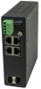
Lantronix SISTP10x0-3xx-LRT Install Guide Install and Connect SFPs via Fiber Optic Cable The Switch lets you install a Small Form-Factor Pluggable (SFP) device of your choice to make a fiber connection via the 100/1000Base-X SFP Ports. See the Lantronix SFP page for SFP models. See the related SFP manual for safety precautions and warnings specific to your SFP model. The SFP ports should use UL Listed Optional Transceiver products, Rated 3.3Vdc, Laser Class 1. 1. Prepare a fiber optic cable with an appropriate connecter. Warning: The fiber optic port contains a Class 1 laser device. When the ports are disconnected, always cover them with the provided plug. Exposed fiber optic ports may cause skin or eye damage. 2. Remove a rubber plug from the Switch and position the SFP device at an SFP slot with the label facing correctly. 3. Carefully slide the SFP device into the slot, aligning it with the internal installation guides. Ensure that the SFP device is firmly seated against the internal mating connector. 4. See the related SFP manual for operating information specific to your particular SFP model. 5. Connect the other end of the cable to the appropriate far end Ethernet port. Note: After the cable is properly connected at both ends, the Switch LED should be functional. See LED Descriptions on page 20 for a description of LED operation. See the related online SFP manual for operating information specific to your particular SFP model. Connect PoE+ Ports via TP Copper Cable The Switch also provides 10/100/1000Base-T. Supported cabling: PoE per IEEE 802.3af PoE supports Cat 3 and Cat 5. PoE per IEEE 802.3at PoE+ supports Cat 5. See "PoE / PoE+ Spec Comparison" on page 15 for more PoE/PoE+ information. 1. Prepare a twisted-pair copper cable. 2. Connect one end of the cable to the Switch. 3. Connect the other end of the cable to a PD, such as a VoIP phone. Note: After the cable is properly connected at both ends, the Switch SYS LED should be functional. See LED Descriptions on page 20 for LED operation details. 33733 Rev. G https://www.lantronix.com/ Page 14 of 31
-
 1
1 -
2
-
3
-
4
-
5
-
6
-
7
-
8
-
 9
9 -
 10
10 -
 11
11 -
 12
12 -
 13
13 -
 14
14 -
 15
15 -
 16
16 -
 17
17 -
 18
18 -
 19
19 -
20
-
21
-
22
-
23
-
24
-
25
-
26
-
27
-
28
-
29
-
30
-
31
 |
 |
