Lantronix XPort XPort - Data Sheet - Page 3
Protocol Support, Recommended PC Board Layout, Dimensions - manual
 |
View all Lantronix XPort manuals
Add to My Manuals
Save this manual to your list of manuals |
Page 3 highlights
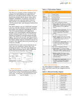
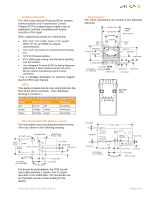
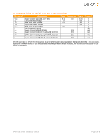
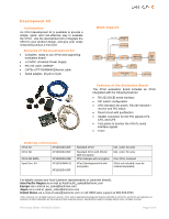
Protocol Support The XPort uses Internet Protocol (IP) for network communications and Transmission Control Protocol (TCP) to assure that no data is lost or duplicated, and that everything sent arrives correctly at the target. Other supported protocols are listed below: • ARP, UDP, TCP, ICMP, Telnet, TFTP, AutoIP, DHCP, HTTP, and SNMP for network communications. • TCP, UDP, and Telnet for connections to the serial port. • TFTP for firmware updates. • IP for addressing, routing, and data block handling over the network. • User Datagram Protocol (UDP) for typical datagram applications in which devices interact with other devices without maintaining a point-to-point connection. * For a complete discussion of protocol support, see the XPort user manual. LEDs The device contains two bi-color LEDs built into the front of the XPort connector. (See dimension drawing for location.) Link LED (Left Side) Activity LED (Right Side) Color Meaning Color Meaning Off No Link Off No Activity Amber 10 Mbps Amber Half-Duplex Green 100 Mbps Green Full-Duplex Recommended PC Board Layout The hole pattern and mounting dimensions for the XPort are shown in the following drawing: O 3.25 O[ 0.128] O 0.90 O[ 0.035] SHIELD TAB O 1.60[ 0.063] 16.05 [0.632] FRONT 8 7 12.30 [0.484] DIMS = mm (in) 2 1 1.27 [0.050] 2.54 [0.100] 3.58 [0.141] 10.84 [0.427] TOLERANCE .XX+/-0.05[0.002] 11.90 [0.468] 2.54 [0.100] 6.35 [0.250] For proper heat dissipation, the PCB should have approximately 1 square inch of copper attached to the shield tabs. The shield tabs are an important source of heat sinking for the device. XPort Data Sheet 910-815G 2/2013 Dimensions The XPort dimensions are shown in the following drawings: 18.25 [0.719] 16.25 [0.640] 11.55 [0.455] FRONT VIEW DIMS = mm (in) LEFT LED 7.15 [0.281] RIGHT LED CONTACT 8 14.50 [0.571] 5.85 [0.230] CONTACT 1 4.03 [0.158] 13.50 [0.531] SHIELD TAB 1.27 [0.050] TOLERANCE 0.40 [0.016] .XX+/-0.20[0.008] SHIELD TAB 3.30 [0.130] 1.85 [0.073] 3.25 [0.128] BOTTOM VIEW 8 2 7 1 1.00 [0.039] FRONT 33.90 [1.335] INTERFACE PINS SHIELD GROUND 0.60 [0.024] 0.35 [0.014] 10.84 [0.427] TOLERANCE .XX+/-0.20[0.008] 11.90 [0.468] SHIELD TAB 2.54 [0.100] 3.20 [0.126] 6.35 [0.250] DIMS = mm (in) Page 3 of 6
-
 1
1 -
 2
2 -
 3
3 -
 4
4 -
 5
5 -
 6
6
 |
 |
