Lantronix XPort XPort-485 - Data Sheet - Page 2
Hardware & Software Description - web pages
 |
View all Lantronix XPort manuals
Add to My Manuals
Save this manual to your list of manuals |
Page 2 highlights
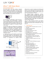
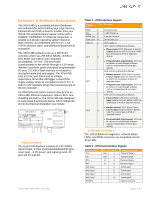
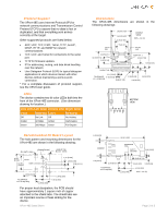
Hardware & Software Description The XPort-485 is a complete solution (hardware and software) for web-enabling your edge devices. Packed into an RJ45 connector smaller than your thumb, this powerful device server comes with a 10BASE-T/100BASE-TX Ethernet connection, a reliable and proven operating system stored in flash memory, an embedded web server, a full TCP/IP protocol stack, and standards-based (AES) encryption. The XPort-485 software runs on a DSTni-EX controller which has 256 KB of SRAM, 16 KB of boot ROM, and a MAC with integrated 10/100BASE-TX PHY. The XPort-485 communicates to the device through a 3.3V serial interface and three general-purpose programmable I/O pins. 512 KB of flash memory is included for storing firmware and web pages. The XPort-485 runs on 3.3V, and has a built-in voltage supervisory circuit that will trigger a reset if the supply voltage drops to unreliable levels (2.7V). A built-in 1.8V regulator drives the processing core of the EX controller. An RJ45 Ethernet cable connects directly into an XPort-485. Ethernet magnetics, status LEDs, and shielding are built in. The XPort-485 was designed to meet class B emissions levels, which makes the electromechanical integration very simple. MAGNETICS Tx LEDs Rx FLASH 25MHz DSTni-EX RJ45 CMOS IO RESET +3.3VDC PCB Interface The 8-pin PCB interface consists of 3.3V CMOS Serial In/Out, 3 Flow Control/Handshake/PIO pins, reset input, +3.3V power, and signal ground. All pins are 5V tolerant. XPort-485 Data Sheet 910-463 Table 1 - PCB Interface Signals Signal Name GND Vcc Reset (In) Data OUT Data IN CP1 Pin 1 2 3 4 5 6 Function Circuit Ground +3.3V Power In External Reset In Serial Data Out Serial Data In CP1 can be configured as follows: • Flow control: RTS (Request to Send) output driven by DSTni's built-in UART for connection to CTS of attached device. • Programmable input/output: CP1 can be driven or read through software control, independent of serial port activity. CP2 can be configured as follows: • Modem control: DTR (Data Terminal Ready) output driven by DSTni's built- in UART for connection to DCD of CP2 7 attached device. • Programmable input/output: CP2 can be driven or read through software control, independent of serial port activity. CP3 can be configured as follows: • Flow control: CTS (Clear to Send) input read by DSTni's built-in UART for connection to RTS of attached device. • Modem control: DCD (Data Carrier CP3 8 Detect) input read by DSTni's built-in UART for connection to DTR of attached device. • Programmable input/output: CP3 can be driven or read through software control, independent of serial port activity. Ethernet Interface The 10/100 Ethernet magnetics, network status LEDs, and RJ45 connector are integrated into the XPort-485. Table 2 - Ethernet Interface Signals Signal Name TX+ TXRX+ RXNot Used Not Used Not Used Not Used SHIELD DIR Out Out In In Contact 1 2 3 6 4 5 7 8 Primary Function Transmit Data + Transmit Data - Receive Data + Receive Data - Terminated Terminated Terminated Terminated Chassis Ground Page 2 of 5
-
 1
1 -
 2
2 -
 3
3 -
 4
4 -
 5
5
 |
 |
