Lantronix XPress-DR-IAP APS: Modbus Protocol User Guide - Page 12
Network/IP Settings, Serial and Mode Settings
 |
View all Lantronix XPress-DR-IAP manuals
Add to My Manuals
Save this manual to your list of manuals |
Page 12 highlights
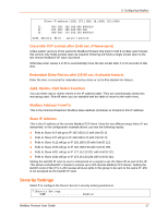
3: Configuring Modbus Network/IP Settings Select 1 to configure the Device Server's network parameters. The following values can be set or changed. To understand and select the appropriate values, consult one of the many TCP/IP books available today and your network administrator. IP Address The IP address must be set to a unique value on your network. If you are not familiar with IP addressing on your network, please consult your network administrator. Please refer to the IAP User Guide for your Device Server for more details about IP addresses. If the IAP Device Server is set to an address already in use, it displays an error code with the LEDs and will not operate properly. If you plan to use DHCP, set the IP to 0.0.0.0 to activate DHCP. Set Gateway IP Address (Y/N) Most users could select N for this case. You only need to choose Y if the IAP Device Server must communicate to remote TCP/IP networks through a router or gateway. If you select Y, you must also enter the IP address of the default gateway within your local network. Set Netmask (N for default) Most users could select N, which causes the IAP Device Server to automatically use the standard netmask appropriate for the IP address entered. Users who want a non-standard netmask need to enter the new subnet mask in the traditional form, for example, 255.255.248.000. Telnet Configuration Password The Telnet configuration password can be set to disable unauthorized access to the setup menu via a Telnet connection to port 9999. To access the setup menu through the serial port, you do not need to enter the password. Serial and Mode Settings Select 2 to change the basic serial parameters. The following values can be set or changed. Attached Device (1=Slave, 2=Master) As mentioned in the introduction, Modbus/RTU devices are defined as either slave or master devices. Type 1 if the attached device is a slave (such as controller or PLC) or 2 if the attached device is a master (such as a computer running graphical human-machine-interface (HMI) software). Serial Protocol (1=Modbus/RTU, 2=Modbus/ASCII) Serial Modbus comes in two forms. Modbus/RTU uses 8-bit data bytes to send binary information. However, some devices cannot handle 8-bit data bytes, so Modbus/ASCII is used. Modbus/ASCII is a slower protocol, where each 8-bit data byte is converted to 2 ASCII characters. Since the IAP Device Server converts both to and from Modbus/TCP fully, you can mix any combination of RTU and ASCII devices on a Modbus/TCP network. So a Modbus/RTU Modbus Protocol User Guide 12
-
 1
1 -
2
-
3
-
4
-
5
-
6
-
 7
7 -
 8
8 -
 9
9 -
 10
10 -
 11
11 -
 12
12 -
 13
13 -
 14
14 -
 15
15 -
 16
16 -
 17
17 -
18
-
19
-
20
-
21
-
22
-
23
-
24
-
25
-
26
-
27
-
28
-
29
-
30
-
31
-
32
-
33
 |
 |
