Lantronix xPico Wi-Fi Shield User Guide - Page 7
xPico Wi-Fi Shield, Table 2-1, xPico Wi-Fi Shield Connectors, Header and Switches
 |
View all Lantronix xPico Wi-Fi Shield manuals
Add to My Manuals
Save this manual to your list of manuals |
Page 7 highlights
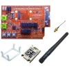
2: xPico Wi-Fi Shield Figure 2-1 xPico Wi-Fi Shield Connectors and Jumpers JP10 and JP11 3.3V and Ground JP3 and JP5 Serial 1 Headers JP1 Current Sense J3 and J4 J1 and J5 Antenna Cable J8 USB Device J9 Serial 2 via USB JP2 CP Header JP6 Power Select Wake Button Default Button Reset Button J2 and Power1 JP17 Button Header J6 and Analog1 Table 2-1 xPico Wi-Fi Shield Connectors, Header and Switches JP Position Label Function Default J7 xPico module socket. J8 Mini USB Type B connects to the xPico module USB device port. Note device port will be enabled on a future software release. J9 Mini USB Type B connects to the xPico module serial port 2 through a USB to serial converter and the JP17 jumper headers. JP1 1-2 UUT PWR Connects to 0.301 ohm current sense resistor R1. Uninstalled Measure voltage on JP1 to calculate module power ti xPico® Wi-Fi® Shield User Guide 7
-
 1
1 -
 2
2 -
 3
3 -
 4
4 -
 5
5 -
 6
6 -
 7
7 -
 8
8 -
 9
9 -
 10
10 -
 11
11 -
 12
12 -
13
-
14
-
15
-
16
-
17
 |
 |
