Lantronix xPico Wi-Fi Shield User Guide - Page 8
xPico Wi-Fi Shield, xPico® Wi-Fi® Shield User Guide
 |
View all Lantronix xPico Wi-Fi Shield manuals
Add to My Manuals
Save this manual to your list of manuals |
Page 8 highlights
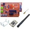
JP JP17 JP17 JP17 JP17 JP17 JP17 JP3 JP5 JP2 JP2 JP2 JP2 JP2 JP2 JP2 JP2 JP2 JP2 JP6 JP10 2: xPico Wi-Fi Shield Position Label Function Default 1-2 WLAN LED Install to use WLAN LED Installed 3-4 WAKE Install to use wake-up input and button,SW1 Installed 5-6 RXD2 Install to route xPico Wi-Fi module second serial port Installed to J9 via the on board USB to serial converter 7-8 TXD2 Install to route xPico Wi-Fi module second serial port Installed to J9 via the on board USB to serial converter 9-10 DEFAULT Install to use Defaults input and button, SW2 S Installed 11-12 RESET Install to use Hardware Reset input and button, SW3 Installed 2-3 TX 2-3 RX Install position 2-3 to connect xPico module TXD1 to Installed Arduino computer board serial RX. Install position 1-2 to connect xPico module RXD1 to Arduino computer board serial RX. Install position 2-3 to connect xPico module RXD1 to Installed Arduino computer board serial TX. Install position 1-2 to connect xPico module TXD1 to Arduino computer board serial TX. 1-2 CP1 Breakout header for CP1, pin 2 does not connect Installed anywhere else on the board. 3-4 CP2 Breakout header for CP2 Installed 5-6 CP3 Breakout header for CP3 Installed 7-8 CP4 Breakout header for CP4 Installed 9-10 CP5 Breakout header for CP5 Installed 11-12 CP6 Breakout header for CP6 Installed 13-14 CP7 Breakout header for CP7 Installed 15-16 CP8 Breakout header for CP8 Installed 17-18 19-20 1-2 1-2 RTS1 CTS1 Power 3.3V Header for RTS1, pin 18 does not connect anywhere Installed else on the board. Header for CTS1, pin 20 does not connect anywhere Installed else on the board. Install pins 1-2 to power shield board from Arduino Installed computer board 3.3V power generated by the on board regulator Not installed xPico® Wi-Fi® Shield User Guide 8
-
 1
1 -
2
-
 3
3 -
 4
4 -
 5
5 -
 6
6 -
 7
7 -
 8
8 -
 9
9 -
 10
10 -
 11
11 -
 12
12 -
 13
13 -
14
-
15
-
16
-
17
 |
 |
