Lenovo 100-15IBY Laptop Hardware Maintenance Manual - Ideapad 100-14IBY, 100-1 - Page 58
Removal steps of heat sink assembly continued
 |
View all Lenovo 100-15IBY Laptop manuals
Add to My Manuals
Save this manual to your list of manuals |
Page 58 highlights
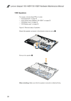
Lenovo ideapad 100-14IBY/100-15IBY Hardware Maintenance Manual Figure 10. Removal steps of heat sink assembly (continued) a When installing: Before you attach the heat sink assembly to the computer, apply thermal grease, at an amount of 0.2 grams, to the part shown in the figure above. Either too much or too little grease application can cause a thermal problem due to imperfect contact with a component. 54
-
 1
1 -
2
-
3
-
4
-
5
-
6
-
7
-
8
-
9
-
10
-
11
-
12
-
13
-
14
-
15
-
16
-
17
-
18
-
19
-
20
-
21
-
22
-
23
-
24
-
25
-
26
-
27
-
28
-
29
-
30
-
31
-
32
-
33
-
34
-
35
-
36
-
37
-
38
-
39
-
40
-
41
-
42
-
43
-
44
-
45
-
46
-
47
-
48
-
49
-
50
-
51
-
52
-
 53
53 -
 54
54 -
 55
55 -
 56
56 -
 57
57 -
 58
58 -
 59
59 -
 60
60 -
 61
61 -
 62
62 -
 63
63 -
64
-
65
-
66
-
67
-
68
-
69
-
70
-
71
-
72
-
73
-
74
-
75
-
76
-
77
-
78
-
79
-
80
-
81
-
82
-
83
-
84
-
85
 |
 |

54
Lenovo ideapad 100-14IBY/100-15IBY Hardware Maintenance Manual
Figure 10. Removal steps of heat sink assembly (continued)
a
When installing:
Before you attach the heat sink assembly to the computer,
apply thermal grease, at an amount of 0.2 grams, to the
part shown in
the figure above. Either too much or too little grease application can cause a
thermal problem due to imperfect contact with a component.