Lenovo A720 Lenovo IdeaCentre A720 Hardware Maintenance Manual (English) - Page 28
Left and right view, Attention, Do not insert 3-inch discs into the optical drive. - usb 3 0
 |
View all Lenovo A720 manuals
Add to My Manuals
Save this manual to your list of manuals |
Page 28 highlights
Left and right view The following illustration shows the location of connectors, controls and components on the left and right side of the computer. 10 9 1 23 4 56 78 1. Air vents 2. USB 3.0 connector 3. HDMI-in connector (selected models only) 4. HDMI-out connector 5. Eject button 6. Optical drive 7. B-CAS card slot (Japan models only) 8. Memory card reader 9. Power button 10. Anti-scratch protector Attention: Do not insert 3-inch discs into the optical drive. 22 IdeaCentre A720Hardware Maintenance Manual
-
 1
1 -
2
-
3
-
4
-
5
-
6
-
7
-
8
-
9
-
10
-
11
-
12
-
13
-
14
-
15
-
16
-
17
-
18
-
19
-
20
-
21
-
22
-
 23
23 -
 24
24 -
 25
25 -
 26
26 -
 27
27 -
 28
28 -
 29
29 -
 30
30 -
 31
31 -
 32
32 -
 33
33 -
34
-
35
-
36
-
37
-
38
-
39
-
40
-
41
-
42
-
43
-
44
-
45
-
46
-
47
-
48
-
49
-
50
-
51
-
52
-
53
-
54
-
55
-
56
-
57
-
58
-
59
-
60
-
61
-
62
-
63
-
64
-
65
-
66
-
67
-
68
-
69
-
70
-
71
-
72
-
73
-
74
-
75
 |
 |

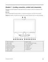
Left and right view
The following illustration shows the location of connectors, controls and components on the left and right
side of the computer.
1. Air vents
6. Optical drive
2. USB 3.0 connector
7. B-CAS card slot (Japan models only)
3. HDMI-in connector (selected models only)
8. Memory card reader
4. HDMI-out connector
9. Power button
5. Eject button
10. Anti-scratch protector
Attention:
Do not insert 3-inch discs into the optical drive.
22
IdeaCentre A720Hardware Maintenance Manual