Lenovo A720 Lenovo IdeaCentre A720 Hardware Maintenance Manual (English) - Page 67
FRU lists, all the cables to the new LED panel.
 |
View all Lenovo A720 manuals
Add to My Manuals
Save this manual to your list of manuals |
Page 67 highlights
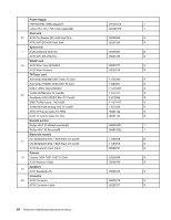
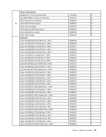
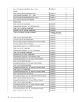
Step 17. Remove the 6 screws that secure the hinge to the middle frame and set the hinge aside. Step 18. To install the new the LED panel: a. Line up the holes on the hinge with the mounting holes on the new middle frame and secure it with 6 screws. b. Attach all the cables to the new LED panel middle frame and front bezel. c. Attach the WLAN card, Bluetooth module, power switch board, converter board, touch control board, scalar board and front function board to the new LED panel middle frame and connect all the cables to the new LED panel. Step 19. Reattach the rear cover to the LED panel. Step 20. Reattach the hinge to the chassis, and reconnect the touch and LED panel cables to the motherboard. Step 21. Reattach the base cover and secure it with the screws. FRU lists This chapter lists the information on the field replaceable units (FRUs). Attention: Be sure to read and understand all the safety information before replacing any FRUs. Notes: FRUs that have a 1 or 2 in the CRU column are Customer Replaceable Units (CRUs). • 1- identifies parts that are fairly simple to replace, requiring few or no tools. • 2- identifies parts that are slightly more difficult to replace. • N-identifies parts that are not to be replaced by the customer. Chapter 8. Replacing hardware 61
-
 1
1 -
2
-
3
-
4
-
5
-
6
-
7
-
8
-
9
-
10
-
11
-
12
-
13
-
14
-
15
-
16
-
17
-
18
-
19
-
20
-
21
-
22
-
23
-
24
-
25
-
26
-
27
-
28
-
29
-
30
-
31
-
32
-
33
-
34
-
35
-
36
-
37
-
38
-
39
-
40
-
41
-
42
-
43
-
44
-
45
-
46
-
47
-
48
-
49
-
50
-
51
-
52
-
53
-
54
-
55
-
56
-
57
-
58
-
59
-
60
-
61
-
 62
62 -
 63
63 -
 64
64 -
 65
65 -
 66
66 -
 67
67 -
 68
68 -
 69
69 -
 70
70 -
 71
71 -
 72
72 -
73
-
74
-
75
 |
 |
