Lenovo Aptiva Hardware Maintenance Manual for NetVista 2179 and 6643 systems - Page 42
Installing, Receiver, Hinge, assembly, removal
 |
View all Lenovo Aptiva manuals
Add to My Manuals
Save this manual to your list of manuals |
Page 42 highlights
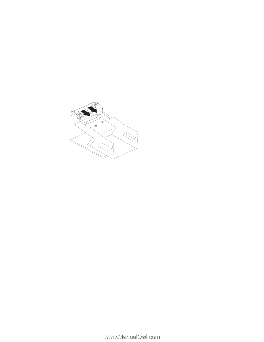
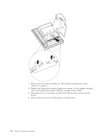
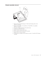
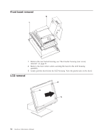
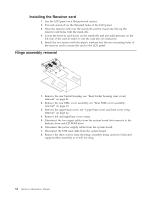
Installing the Receiver card 1. Lay the LCD panel on a flat protected surface. 2. Put each stand-off on the threaded holes of the LCD panel. 3. Place the receiver card over the stand-offs and by visual site line up the receiver card holes with the stand-offs. 4. Lower the receiver card down on the stand-offs and put mild pressure on the left side of the card in order to seat the card into its connectors. 5. Install the two screws with the plastic washers into the two mounting holes of the receiver card to secure the card to the LCD panel. Hinge assembly removal 1. Remove the rear bucket housing, see "Rear bucket housing (rear cover) removal" on page 21. 2. Remove the rear EMC cover assembly, see "Rear EMC cover assembly removal" on page 23. 3. Remove the upper base cover, see "Upper base cover and base cover wing removal" on page 22. 4. Remove left and right base cover wings. 5. Disconnect the two signal cables from the system board that connects to the diskette drive and CD-ROM drive. 6. Disconnect the power supply cables from the system board. 7. Disconnect the USB card cable from the system board. 8. Remove the three screws from the hinge assembly being careful to hold and support either assembly so it will not drop. 34 Hardware Maintenance Manual
-
 1
1 -
2
-
3
-
4
-
5
-
6
-
7
-
8
-
9
-
10
-
11
-
12
-
13
-
14
-
15
-
16
-
17
-
18
-
19
-
20
-
21
-
22
-
23
-
24
-
25
-
26
-
27
-
28
-
29
-
30
-
31
-
32
-
33
-
34
-
35
-
36
-
 37
37 -
 38
38 -
 39
39 -
 40
40 -
 41
41 -
 42
42 -
 43
43 -
 44
44 -
 45
45 -
 46
46 -
 47
47 -
48
-
49
-
50
-
51
-
52
-
53
-
54
-
55
-
56
-
57
-
58
-
59
-
60
-
61
-
62
-
63
-
64
-
65
-
66
-
67
-
68
-
69
-
70
-
71
-
72
-
73
-
74
-
75
-
76
-
77
-
78
-
79
-
80
-
81
-
82
-
83
-
84
-
85
-
86
-
87
-
88
-
89
-
90
-
91
-
92
-
93
-
94
-
95
-
96
-
97
-
98
-
99
-
100
-
101
-
102
-
103
-
104
-
105
-
106
-
107
-
108
-
109
-
110
-
111
-
112
-
113
-
114
-
115
-
116
-
117
-
118
-
119
-
120
-
121
-
122
-
123
-
124
-
125
-
126
-
127
-
128
 |
 |