Lenovo B345 IdeaCentre B345-B545 All-In-One Hardware Maintenance Manual
Lenovo B345 Manual
 |
View all Lenovo B345 manuals
Add to My Manuals
Save this manual to your list of manuals |
Lenovo B345 manual content summary:
- Lenovo B345 | IdeaCentre B345-B545 All-In-One Hardware Maintenance Manual - Page 1
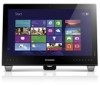
IdeaCentre B345-B545 All-In-One Hardware Maintenance Manual ideaideaideaCentreidea Machine Types: 10098/2567 [B345], 10100/4749 [B545] - Lenovo B345 | IdeaCentre B345-B545 All-In-One Hardware Maintenance Manual - Page 2
- Lenovo B345 | IdeaCentre B345-B545 All-In-One Hardware Maintenance Manual - Page 3
IdeaCentre B345-B545 All-In-One Hardware Maintenance Manual Machine Types: 10098/2567 [B345], 10100/4749 [B545] - Lenovo B345 | IdeaCentre B345-B545 All-In-One Hardware Maintenance Manual - Page 4
First Edition (September 2012)11th © Copyright Lenovo 2012. LIMITED AND RESTRICTED RIGHTS NOTICE: If data or software are delivered pursuant a General Services Administration "GSA" contract, use, reproduction, or disclosure is subject to restrictions set forth in Contract No. GS-35F-05925 - Lenovo B345 | IdeaCentre B345-B545 All-In-One Hardware Maintenance Manual - Page 5
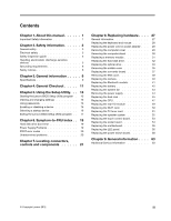
a device 15 Selecting a startup device 16 Exiting the Lenovo BIOS Setup Utility program . . 17 Chapter 6. Symptom-to-FRU Index . . 19 Hard disk drive boot error 19 Power Supply Problems 19 POST error codes 20 Undetermined problems 20 Chapter 7. Locating connectors, controls and components 21 - Lenovo B345 | IdeaCentre B345-B545 All-In-One Hardware Maintenance Manual - Page 6
iv IdeaCentre B345-B545 All-In-OneHardware Maintenance Manual - Lenovo B345 | IdeaCentre B345-B545 All-In-One Hardware Maintenance Manual - Page 7
manual This manual contains service and reference information for IdeaCentre B345-B545 All-In-One computers listed on the cover. It is intended only for trained servicers who are familiar with Lenovo computer products. Before servicing a Lenovo avant d'exécuter les instructions. Lesen Sie unbedingt - Lenovo B345 | IdeaCentre B345-B545 All-In-One Hardware Maintenance Manual - Page 8
2 IdeaCentre B345-B545 All-In-OneHardware Maintenance Manual - Lenovo B345 | IdeaCentre B345-B545 All-In-One Hardware Maintenance Manual - Page 9
safe place, away from all personnel, while you are servicing the machine. • Keep your tool case away from power cords, telecommunication systems, networks, and modems before you open the computer covers, unless instructed otherwise in the installation and configuration procedures. © Copyright Lenovo - Lenovo B345 | IdeaCentre B345-B545 All-In-One Hardware Maintenance Manual - Page 10
you work with very high voltages; these instructions are in the safety sections of maintenance service the following parts with the power on when they are removed from their normal operating places in a machine: - Power Switch off power. 4 IdeaCentre B345-B545 All-In-OneHardware Maintenance Manual - Lenovo B345 | IdeaCentre B345-B545 All-In-One Hardware Maintenance Manual - Page 11
had required safety items installed to protect users and service personnel from injury. This guide addresses only those items. However, good judgment should correcting the problem. Consider these conditions and the safety hazards they present: • Electrical hazards, especially primary power (primary - Lenovo B345 | IdeaCentre B345-B545 All-In-One Hardware Maintenance Manual - Page 12
service power instructed otherwise in the installation and configuration procedures. • Connect and disconnect cables as described in the following table when installing, moving, or opening covers on this product or attached devices. 6 IdeaCentre B345-B545 All-In-OneHardware Maintenance Manual - Lenovo B345 | IdeaCentre B345-B545 All-In-One Hardware Maintenance Manual - Page 13
to connectors. 4. Attach power cords to outlet. 5. Turn device ON. To Disconnect 1. Turn everything OFF. 2. First, remove power cords from outlet. 3. product could result in exposure to hazardous laser radiation. There are no serviceable parts inside the device. • Use of controls or adjustments or - Lenovo B345 | IdeaCentre B345-B545 All-In-One Hardware Maintenance Manual - Page 14
power cord. To remove all electrical current from the device, ensure that all power cords are disconnected from the power source. 2 1 CAUTION: Do not place any object weighing more than 82 kg (180 lbs.) on top of rack-mounted devices. 8 IdeaCentre B345-B545 All-In-OneHardware Maintenance Manual - Lenovo B345 | IdeaCentre B345-B545 All-In-One Hardware Maintenance Manual - Page 15
supported by this publication. Specifications This section lists the physical specifications for your computer. This section lists the physical specifications for your computer. Type IdeaCentre B345 Electrical input: Input voltage: 90V-264V(AC) Input frequency: 47Hz-63Hz © Copyright Lenovo 2012 9 - Lenovo B345 | IdeaCentre B345-B545 All-In-One Hardware Maintenance Manual - Page 16
10 IdeaCentre B345-B545 All-In-OneHardware Maintenance Manual - Lenovo B345 | IdeaCentre B345-B545 All-In-One Hardware Maintenance Manual - Page 17
cause of the problem: 1. Power-off the computer and all external devices. 2. Check all cables and power cords. 3. Set all display controls to the middle position. 4. Power-on all external devices. 5. Power-on the computer. • Look for displayed error codes • Look for readable instructions or a main - Lenovo B345 | IdeaCentre B345-B545 All-In-One Hardware Maintenance Manual - Page 18
12 IdeaCentre B345-B545 All-In-OneHardware Maintenance Manual - Lenovo B345 | IdeaCentre B345-B545 All-In-One Hardware Maintenance Manual - Page 19
system and turn off the computer. 2. Press and hold the F1 key then turn on the computer. When the Lenovo BIOS Setup Utility program is displayed, release the F1 key. Note: If a Power-On Password or an Administrator Password has been set, the Setup Utility program menu is not displayed until you - Lenovo B345 | IdeaCentre B345-B545 All-In-One Hardware Maintenance Manual - Page 20
the Lenovo BIOS Setup Utility program until a valid password is typed from the keyboard. Setting, changing, or deleting a Power-On Password Note: A password can be any combination of letters and numbers up to 16 character (a-z, and 0-9). 14 IdeaCentre B345-B545 All-In-OneHardware Maintenance Manual - Lenovo B345 | IdeaCentre B345-B545 All-In-One Hardware Maintenance Manual - Page 21
installed. To change a Power-On Password, do the following: 1. Start the Lenovo BIOS Setup Utility program (See "Starting the Lenovo BIOS Setup Utility program" be used. ATA Drive Setup Select IDE or ACHI mode. Device driver support is required for ACHI mode. Depending on how the hard disk image - Lenovo B345 | IdeaCentre B345-B545 All-In-One Hardware Maintenance Manual - Page 22
sequence. 5. Return to the Lenovo BIOS Setup Utility program menu and select the Exit option. 6. Select Save changes and Exit from the menu. Notes: a. If you do not want to save the settings, select Discard changes and Exit from the menu. 16 IdeaCentre B345-B545 All-In-OneHardware Maintenance Manual - Lenovo B345 | IdeaCentre B345-B545 All-In-One Hardware Maintenance Manual - Page 23
or changing settings, press the Esc key to return to the Lenovo BIOS Setup Utility program main menu. You might have to press the reset window shows, select the Yes button, and then press the Enter key to exit the Lenovo BIOS Setup Utility program. • If you do not want to save the settings, select - Lenovo B345 | IdeaCentre B345-B545 All-In-One Hardware Maintenance Manual - Page 24
18 IdeaCentre B345-B545 All-In-OneHardware Maintenance Manual - Lenovo B345 | IdeaCentre B345-B545 All-In-One Hardware Maintenance Manual - Page 25
on page 11. This index can also be used to help you decide which FRUs to have available when servicing a computer. If you are unable to correct the problem using this index, go to "Undetermined problems" on page 20. Notes: • If you have both an error message and an incorrect audio response, diagnose - Lenovo B345 | IdeaCentre B345-B545 All-In-One Hardware Maintenance Manual - Page 26
Disk drive 3. Power-on the computer to re-test the system. 4. Repeat steps 1 through 3 until you find the failing device or component. If all devices and components have been removed and the problem continues, replace the system board. 20 IdeaCentre B345-B545 All-In-OneHardware Maintenance Manual - Lenovo B345 | IdeaCentre B345-B545 All-In-One Hardware Maintenance Manual - Page 27
mode / HDMI-in / AV-in switch 14. Monitor On/Off Attention: The effective range of the Built-in IR Emitter is 10 feet (3m). © Copyright Lenovo 2012 21 - Lenovo B345 | IdeaCentre B345-B545 All-In-One Hardware Maintenance Manual - Page 28
left and right side of the computer. 1 2 1. Optical drive 2. TV buttons (selected models only) 3. USB connector 4. Headphone port 3 4 5 6 7 8 5. Microphone port 6. USB connector 7. Memory card reader 8. Power button 22 IdeaCentre B345-B545 All-In-OneHardware Maintenance Manual - Lenovo B345 | IdeaCentre B345-B545 All-In-One Hardware Maintenance Manual - Page 29
port 2. USB connectors 3. HDMI-OUT connector 4. HDMI-IN connector (selected models only) 2 34 5 5. AV-IN connectors (selected models only) 6. TV tuner ports (selected models only) 7. Power connector 8. Air vents (do not block) Chapter 7. Locating connectors, controls and components 23 - Lenovo B345 | IdeaCentre B345-B545 All-In-One Hardware Maintenance Manual - Page 30
5. EMI cover 6. Chassis 7. LED panel 8. Front bezel 9. Glass 10. Rear I/O module 11. Power supply 12. Motherboard 13. Hard disk drive 11 12 14. Optical disk drive 15. Hardware TV Scale Board board 25. Touch module 26. Bluetooth module 24 IdeaCentre B345-B545 All-In-OneHardware Maintenance Manual - Lenovo B345 | IdeaCentre B345-B545 All-In-One Hardware Maintenance Manual - Page 31
board in your computer. It provides basic computing functions and supports a variety of devices that are factory-installed or that Fi card connector 10. TV-Tuner card connector 11. Rear I/O connector 12. Power switch board connector 13. Speaker connector 14. Front LED indicator board connector 21 - Lenovo B345 | IdeaCentre B345-B545 All-In-One Hardware Maintenance Manual - Page 32
the digital hardware TV board. (DVB-T type) 1 2 3 4 5 6 7 1. LVDS Connector 2. Converter Connector 3. TV Function Connector 4. Mother Board Connector 5. Tuner Board Connector 6. Fan Connector 7. Debug Port 26 IdeaCentre B345-B545 All-In-OneHardware Maintenance Manual - Lenovo B345 | IdeaCentre B345-B545 All-In-One Hardware Maintenance Manual - Page 33
with your computer. To obtain copies of the Safety and Warranty Guide, go to the Support Web site at: http://consumersupport.lenovo.com. Note: Use only parts provided by Lenovo. General information Pre-disassembly instructions Before proceeding with the disassembly procedure, make sure that you do - Lenovo B345 | IdeaCentre B345-B545 All-In-One Hardware Maintenance Manual - Page 34
to 5 minutes to let it cool down before removing the cover. To replace the power cord and power adapter: Step 1. Remove any media (diskettes, CDs, DVDs, or memory cards) from Locate the connector for the power cord. Refer to "Rear view". 28 IdeaCentre B345-B545 All-In-OneHardware Maintenance Manual - Lenovo B345 | IdeaCentre B345-B545 All-In-One Hardware Maintenance Manual - Page 35
the new power cord to the same connector as shown. Removing the computer cover Attention: Turn off the computer and wait 3 to 5 minutes to let it cool down before removing the cover. Note: It may be helpful to place the computer face-down on a soft flat surface for this procedure. Lenovo recommends - Lenovo B345 | IdeaCentre B345-B545 All-In-One Hardware Maintenance Manual - Page 36
procedure, it helps to place the computer face-down on a soft flat surface. Lenovo recommends that you use a blanket, towel, or other soft cloth to protect the screen surface from scratches or other damage. To remove the computer stand: 30 IdeaCentre B345-B545 All-In-OneHardware Maintenance Manual - Lenovo B345 | IdeaCentre B345-B545 All-In-One Hardware Maintenance Manual - Page 37
shut down the operating system, and turn off the computer and all attached devices. Unplug all power cords from electrical outlets. Disconnect all cables attached to the computer. This includes power cords, input/output (I/O) cables, and any other cables that are connected to the computer. Refer to - Lenovo B345 | IdeaCentre B345-B545 All-In-One Hardware Maintenance Manual - Page 38
. Lenovo recommends power cords, input/output (I/O) cables, and any other cables that are connected to the computer. Refer to "Left and right view" and "Rear view" for help with locating the various connectors. Remove the rear cover. Refer to "Removing the rear cover". 32 IdeaCentre B345 - Lenovo B345 | IdeaCentre B345-B545 All-In-One Hardware Maintenance Manual - Page 39
shut down the operating system, and turn off the computer and all attached devices. Unplug all power cords from electrical outlets. Disconnect all cables attached to the computer. This includes power cords, input/output (I/O) cables, and any other cables that are connected to the computer. Refer to - Lenovo B345 | IdeaCentre B345-B545 All-In-One Hardware Maintenance Manual - Page 40
to the metal bracket. 1 Step 8. Use a small flat head screwdriver to press and push out the pins that secure the cover to the disk. 2 3 34 IdeaCentre B345-B545 All-In-OneHardware Maintenance Manual - Lenovo B345 | IdeaCentre B345-B545 All-In-One Hardware Maintenance Manual - Page 41
place the computer face-down on a soft flat surface for this procedure. Lenovo recommends that you use a blanket, towel, or other soft cloth to protect devices. Unplug all power cords from electrical outlets. Disconnect all cables attached to the computer. This includes power cords, input/output - Lenovo B345 | IdeaCentre B345-B545 All-In-One Hardware Maintenance Manual - Page 42
Step 7. Remove the eight screws that secure the middle cover to the chassis. 1 1 1 1 1 1 1 1 1 Step 8. Push up the middle cover upward with two hands to remove it from pins. 2 23 36 IdeaCentre B345-B545 All-In-OneHardware Maintenance Manual - Lenovo B345 | IdeaCentre B345-B545 All-In-One Hardware Maintenance Manual - Page 43
place the computer face-down on a soft flat surface for this procedure. Lenovo recommends that you use a blanket, towel, or other soft cloth to devices. Unplug all power cords from electrical outlets. Disconnect all cables attached to the computer. This includes power cords, input/output - Lenovo B345 | IdeaCentre B345-B545 All-In-One Hardware Maintenance Manual - Page 44
Step 8. Push the pins to release the converter. 1 1 1 1 Step 9. Disconnect the two cables from the converter board. 2 Step 10. Lift up the converter board to remove it. 2 2 38 IdeaCentre B345-B545 All-In-OneHardware Maintenance Manual - Lenovo B345 | IdeaCentre B345-B545 All-In-One Hardware Maintenance Manual - Page 45
to place the computer face-down on a soft flat surface for this procedure. Lenovo recommends that you use a blanket, towel, or other soft cloth to protect 2. Unplug all power cords from electrical outlets. Step 3. Disconnect all cables attached to the computer. This includes power cords, input/output - Lenovo B345 | IdeaCentre B345-B545 All-In-One Hardware Maintenance Manual - Page 46
computer face-down on a soft flat surface for this procedure. Lenovo recommends that you use a blanket, towel, or other soft all power cords from electrical outlets. Disconnect all cables attached to the computer. This includes power cords, IdeaCentre B345-B545 All-In-OneHardware Maintenance Manual - Lenovo B345 | IdeaCentre B345-B545 All-In-One Hardware Maintenance Manual - Page 47
place the computer face-down on a soft flat surface for this procedure. Lenovo recommends that you use a blanket, towel, or other soft cloth to devices. Unplug all power cords from electrical outlets. Disconnect all cables attached to the computer. This includes power cords, input/output - Lenovo B345 | IdeaCentre B345-B545 All-In-One Hardware Maintenance Manual - Page 48
computer face-down on a soft flat surface for this procedure. Lenovo recommends that you use a blanket, towel, or other soft all power cords from electrical outlets. Disconnect all cables attached to the computer. This includes power cords, IdeaCentre B345-B545 All-In-OneHardware Maintenance Manual - Lenovo B345 | IdeaCentre B345-B545 All-In-One Hardware Maintenance Manual - Page 49
place the computer face-down on a soft flat surface for this procedure. Lenovo recommends that you use a blanket, towel, or other soft cloth to protect devices. Unplug all power cords from electrical outlets. Disconnect all cables attached to the computer. This includes power cords, input/output - Lenovo B345 | IdeaCentre B345-B545 All-In-One Hardware Maintenance Manual - Page 50
the system fan with five screws. c. Connect the fan power cable to the connectors on the motherboard. Step 12. Reattach power supply Attention: Turn off the computer and wait 3 to 5 minutes to let it cool down before removing the cover. 44 IdeaCentre B345-B545 All-In-OneHardware Maintenance Manual - Lenovo B345 | IdeaCentre B345-B545 All-In-One Hardware Maintenance Manual - Page 51
to place the computer face-down on a soft flat surface for this procedure. Lenovo recommends that you use a blanket, towel, or other soft cloth to protect the computer screen from scratches or other damage. To remove the power supply: Step 1. Remove any media (disks, CDs, or memory cards) from the - Lenovo B345 | IdeaCentre B345-B545 All-In-One Hardware Maintenance Manual - Page 52
down on a soft flat surface for this procedure. Lenovo recommends that you use a blanket, towel, or other Unplug all power cords from electrical outlets. Step 3. Disconnect all cables attached to the computer. This includes power cords, input IdeaCentre B345-B545 All-In-OneHardware Maintenance Manual - Lenovo B345 | IdeaCentre B345-B545 All-In-One Hardware Maintenance Manual - Page 53
down the operating system, and turn off the computer and all attached devices. Step 2. Unplug all power cords from electrical outlets. Step 3. Disconnect all cables attached to the computer. This includes power cords, input/output (I/O) cables, and any other cables that are connected to the computer - Lenovo B345 | IdeaCentre B345-B545 All-In-One Hardware Maintenance Manual - Page 54
the tabs in the microprocessor socket. Important: To avoid damaging the microprocessor contacts, keep the microprocessor completely level while installing it into the socket. 48 IdeaCentre B345-B545 All-In-OneHardware Maintenance Manual - Lenovo B345 | IdeaCentre B345-B545 All-In-One Hardware Maintenance Manual - Page 55
the computer face-down on a soft flat surface for this procedure. Lenovo recommends that you use a blanket, towel, or other soft cloth to protect attached devices. Unplug all power cords from electrical outlets. Disconnect all cables attached to the computer. This includes power cords, input/output - Lenovo B345 | IdeaCentre B345-B545 All-In-One Hardware Maintenance Manual - Page 56
Note: Turn off the computer and wait 3 to 5 minutes to let it cool down before removing the cover. To replace the Wi-Fi card: 50 IdeaCentre B345-B545 All-In-OneHardware Maintenance Manual - Lenovo B345 | IdeaCentre B345-B545 All-In-One Hardware Maintenance Manual - Page 57
shut down the operating system, and turn off the computer and all attached devices. Unplug all power cords from electrical outlets. Disconnect all cables attached to the computer. This includes power cords, input/output (I/O) cables, and any other cables that are connected to the computer. Refer to - Lenovo B345 | IdeaCentre B345-B545 All-In-One Hardware Maintenance Manual - Page 58
computer and all attached devices. Unplug all power cords from electrical outlets. Disconnect all cables attached to the computer. This includes power cords, input/output (I/O) cables, and any cover. Refer to "Removing the EMI cover". 52 IdeaCentre B345-B545 All-In-OneHardware Maintenance Manual - Lenovo B345 | IdeaCentre B345-B545 All-In-One Hardware Maintenance Manual - Page 59
shut down the operating system, and turn off the computer and all attached devices. Unplug all power cords from electrical outlets. Disconnect all cables attached to the computer. This includes power cords, input/output (I/O) cables, and any other cables that are connected to the computer. Refer to - Lenovo B345 | IdeaCentre B345-B545 All-In-One Hardware Maintenance Manual - Page 60
computer and all attached devices. Unplug all power cords from electrical outlets. Disconnect all cables attached to the computer. This includes power cords, input/output (I/O) cables, and module. Refer to "Replacing the rear I/O module". 54 IdeaCentre B345-B545 All-In-OneHardware Maintenance Manual - Lenovo B345 | IdeaCentre B345-B545 All-In-One Hardware Maintenance Manual - Page 61
down the operating system, and turn off the computer and all attached devices. Step 2. Unplug all power cords from electrical outlets. Step 3. Disconnect all cables attached to the computer. This includes power cords, input/output (I/O) cables, and any other cables that are connected to the computer - Lenovo B345 | IdeaCentre B345-B545 All-In-One Hardware Maintenance Manual - Page 62
rear cover. Replacing the LED panel Note: Turn off the computer and wait 3 to 5 minutes to let it cool down before removing the cover. 56 IdeaCentre B345-B545 All-In-OneHardware Maintenance Manual - Lenovo B345 | IdeaCentre B345-B545 All-In-One Hardware Maintenance Manual - Page 63
the computer face-down on a soft flat surface for this procedure. Lenovo recommends that you use a blanket, towel, or other soft cloth . Step 2. Unplug all power cords from electrical outlets. Step 3. Disconnect all cables attached to the computer. This includes power cords, input/output (I/O) - Lenovo B345 | IdeaCentre B345-B545 All-In-One Hardware Maintenance Manual - Page 64
the front indicator board cable from the connector on the motherboard. Step 17. Disconnect the power switch board cable from the connector on the motherboard. Step 18. Remove the eight screws cable from the connector on the LED panel. 58 IdeaCentre B345-B545 All-In-OneHardware Maintenance Manual - Lenovo B345 | IdeaCentre B345-B545 All-In-One Hardware Maintenance Manual - Page 65
the chassis into position. d. Connect the converter cable to the converter. e. Connect the front function board cable, front indicator board cable and the power switch board cable to the connectors on the motherboard. f. Reattach the Wi-Fi antenna cables back to the front bezel. g. Secure the new - Lenovo B345 | IdeaCentre B345-B545 All-In-One Hardware Maintenance Manual - Page 66
and wait 3 to 5 minutes to let it cool down before removing the cover. To replace the power switch board Step 1. Remove any media (disks, CDs, DVDs, or memory cards) from the drives, Detach the Wi-Fi antenna cables from the front bezel. 60 IdeaCentre B345-B545 All-In-OneHardware Maintenance Manual - Lenovo B345 | IdeaCentre B345-B545 All-In-One Hardware Maintenance Manual - Page 67
from the connector on the motherboard. Step 16. Disconnect the front indicator board cable from the connector on the motherboard. Step 17. Disconnect the power switch board cable from the connector on the motherboard. Step 18. Remove the eight screws that secure the chassis to the front bezel. Step - Lenovo B345 | IdeaCentre B345-B545 All-In-One Hardware Maintenance Manual - Page 68
the converter. e. Connect the front function board cable, front indicator board cable and the power switch board cable to the connectors on the motherboard. f. Reattach the Wi-Fi antenna cables drive, computer stand and the rear cover. 62 IdeaCentre B345-B545 All-In-OneHardware Maintenance Manual - Lenovo B345 | IdeaCentre B345-B545 All-In-One Hardware Maintenance Manual - Page 69
supported by this publication. Additional Service Information This chapter provides additional information that the service representative might find helpful. Power management Power management reduces the power LAN: This feature allows LAN adapter card to wake the System. © Copyright Lenovo 2012 63
-
 1
1 -
 2
2 -
 3
3 -
 4
4 -
 5
5 -
 6
6 -
 7
7 -
8
-
9
-
10
-
11
-
12
-
13
-
14
-
15
-
16
-
17
-
18
-
19
-
20
-
21
-
22
-
23
-
24
-
25
-
26
-
27
-
28
-
29
-
30
-
31
-
32
-
33
-
34
-
35
-
36
-
37
-
38
-
39
-
40
-
41
-
42
-
43
-
44
-
45
-
46
-
47
-
48
-
49
-
50
-
51
-
52
-
53
-
54
-
55
-
56
-
57
-
58
-
59
-
60
-
61
-
62
-
63
-
64
-
65
-
66
-
67
-
68
-
69
 |
 |

IdeaCentre B345–B545 All-In-One
Hardware Maintenance Manual
Machine Types: 10098/2567 [B345], 10100/4749 [B545]