Lenovo B345 IdeaCentre B345-B545 All-In-One Hardware Maintenance Manual - Page 28
Left and right view, The following illustration shows the location of connectors
 |
View all Lenovo B345 manuals
Add to My Manuals
Save this manual to your list of manuals |
Page 28 highlights
Left and right view The following illustration shows the location of connectors, controls and components on the left and right side of the computer. 1 2 1. Optical drive 2. TV buttons (selected models only) 3. USB connector 4. Headphone port 3 4 5 6 7 8 5. Microphone port 6. USB connector 7. Memory card reader 8. Power button 22 IdeaCentre B345-B545 All-In-OneHardware Maintenance Manual
-
 1
1 -
2
-
3
-
4
-
5
-
6
-
7
-
8
-
9
-
10
-
11
-
12
-
13
-
14
-
15
-
16
-
17
-
18
-
19
-
20
-
21
-
22
-
 23
23 -
 24
24 -
 25
25 -
 26
26 -
 27
27 -
 28
28 -
 29
29 -
 30
30 -
 31
31 -
 32
32 -
 33
33 -
34
-
35
-
36
-
37
-
38
-
39
-
40
-
41
-
42
-
43
-
44
-
45
-
46
-
47
-
48
-
49
-
50
-
51
-
52
-
53
-
54
-
55
-
56
-
57
-
58
-
59
-
60
-
61
-
62
-
63
-
64
-
65
-
66
-
67
-
68
-
69
 |
 |

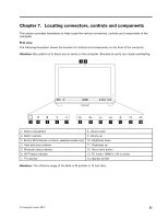
Left and right view
The following illustration shows the location of connectors, controls and components on the left and right
side of the computer.
1. Optical drive
5. Microphone port
2. TV buttons (selected models only)
6. USB connector
3. USB connector
7. Memory card reader
4. Headphone port
8. Power button
22
IdeaCentre B345–B545 All-In-OneHardware Maintenance Manual