Lenovo B540 Lenovo IdeaCentre B540-B540P Hardware Maintenance Manual - Page 55
Replacing the Wi-Fi card, Line the new I/O module up with the chassis then secure it with the screws.
 |
View all Lenovo B540 manuals
Add to My Manuals
Save this manual to your list of manuals |
Page 55 highlights
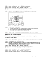
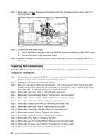
Step 10. Lift up the rear I/O module. Step 11. Disconnect the TV antenna cable from the rear I/O module by removing the 2 screws. Step 12. Remove the 2 screws that secure the rear I/O module to the metal bracket. 1 2 1 2 Step 13. Lift the rear I/O module up from connectors on the motherboard then slide it out. Step 14. To install the new rear I/O module: a. Line the new I/O module up then slide it into the metal bracket. b. Secure the new I/O module to the bracket with the 2 screws. c. Reattach the TV antenna cable to the rear I/O module. d. Line the new I/O module up with the chassis then secure it with the screws. Step 15. Reattach the EMI cover, middle cover, optical drive, computer stand and the rear cover. Replacing the Wi-Fi card Note: Turn off the computer and wait 3 to 5 minutes to let it cool down before removing the cover. To replace the Wi-Fi card: Step 1. Remove any media (disks, CDs, DVDs, or memory cards) from the drives, shut down the operating system, and turn off the computer and all attached devices. Chapter 8. Replacing hardware 49
-
 1
1 -
2
-
3
-
4
-
5
-
6
-
7
-
8
-
9
-
10
-
11
-
12
-
13
-
14
-
15
-
16
-
17
-
18
-
19
-
20
-
21
-
22
-
23
-
24
-
25
-
26
-
27
-
28
-
29
-
30
-
31
-
32
-
33
-
34
-
35
-
36
-
37
-
38
-
39
-
40
-
41
-
42
-
43
-
44
-
45
-
46
-
47
-
48
-
49
-
 50
50 -
 51
51 -
 52
52 -
 53
53 -
 54
54 -
 55
55 -
 56
56 -
 57
57 -
 58
58 -
 59
59 -
 60
60 -
61
-
62
-
63
-
64
-
65
-
66
-
67
-
68
-
69
-
70
-
71
 |
 |
