Lenovo B540 Lenovo IdeaCentre B540-B540P Hardware Maintenance Manual - Page 63
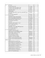
FRU lists, Model, DIP 1, LTM230HT10 M01, LM230WF5-TLF1, M230HGE-L20 C1
 |
View all Lenovo B540 manuals
Add to My Manuals
Save this manual to your list of manuals |
Page 63 highlights
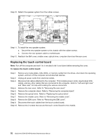
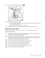
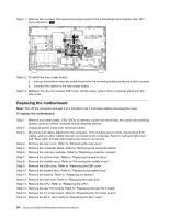
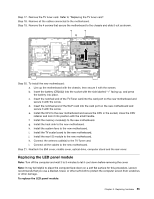
Step 25. Remove the four screws that secure the two feet to the chassis, lift up the two feet and put them aside. Step 26. To install the new the LED panel module: a. Attached the two feet to the chassis and secure them with the four screws. b. Attach the Bluetooth module to the front bezel. c. Attach the motherboard to the chassis, and secure it with the screws. d. Attach the Wi-Fi antenna cables to the front bezel. e. Install the hard disk drive and optical disk drive data and power connectors to the chassis. f. Attach the touch control board, camera, Wi-Fi card, rear I/O module, scalar board, TV-Tuner card, power supply, speaker system, CPU, heat-sink module, battery, memory, system fan, converter board, hard disk drive, to the motherboard and chassis. g. To get the best display quality for your monitor, adjust the PTV139 DIP switch settings on the TV scalar board according the below chart for different panel models: Note: 1=OFF 0=ON Size Model DIP 1 DIP 2 DIP 3 DIP 4 LTM230HT10 M01 1 1 1 0 LTM230HT10 M02 1 1 0 1 23'LED LM230WF5-TLF1 1 1 0 0 M230HGE-L20 C1 1 0 1 1 23'FPR LM230WF8-TLA1 1 0 1 0 Step 27. Reattach the EMI cover, middle cover, optical drive, computer stand and the rear cover. FRU lists This chapter lists the information on the field replaceable units (FRUs). Chapter 8. Replacing hardware 57
-
 1
1 -
2
-
3
-
4
-
5
-
6
-
7
-
8
-
9
-
10
-
11
-
12
-
13
-
14
-
15
-
16
-
17
-
18
-
19
-
20
-
21
-
22
-
23
-
24
-
25
-
26
-
27
-
28
-
29
-
30
-
31
-
32
-
33
-
34
-
35
-
36
-
37
-
38
-
39
-
40
-
41
-
42
-
43
-
44
-
45
-
46
-
47
-
48
-
49
-
50
-
51
-
52
-
53
-
54
-
55
-
56
-
57
-
 58
58 -
 59
59 -
 60
60 -
 61
61 -
 62
62 -
 63
63 -
 64
64 -
 65
65 -
 66
66 -
 67
67 -
 68
68 -
69
-
70
-
71
 |
 |
