Lenovo C360 Lenovo C360-365 All-In-One Computer Hardware Maintenance Manual
Lenovo C360 Manual
 |
View all Lenovo C360 manuals
Add to My Manuals
Save this manual to your list of manuals |
Lenovo C360 manual content summary:
- Lenovo C360 | Lenovo C360-365 All-In-One Computer Hardware Maintenance Manual - Page 1
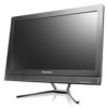
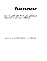
Lenovo C360-365 All-In-One ComputerHardware Maintenance Manual ideaideaideaCentreidea Machine Types: 10147/F0AB [C360]; 10148/F0AC [C365] - Lenovo C360 | Lenovo C360-365 All-In-One Computer Hardware Maintenance Manual - Page 2
- Lenovo C360 | Lenovo C360-365 All-In-One Computer Hardware Maintenance Manual - Page 3
Lenovo C360-365 All-In-One Computer Hardware Maintenance Manual Machine Types: 10147/F0AB [C360]; 10148/F0AC [C365] - Lenovo C360 | Lenovo C360-365 All-In-One Computer Hardware Maintenance Manual - Page 4
First Edition (October 2013)21st © Copyright Lenovo 2013. LIMITED AND RESTRICTED RIGHTS NOTICE: If data or software are delivered pursuant a General Services Administration "GSA" contract, use, reproduction, or disclosure is subject to restrictions set forth in Contract No. GS-35F-05925 - Lenovo C360 | Lenovo C360-365 All-In-One Computer Hardware Maintenance Manual - Page 5
device 15 Selecting a startup device 16 Exiting the Lenovo BIOS Setup Utility program . . 17 Chapter 6. Symptom-to-FRU Index . . 19 Hard disk drive boot error 19 Power Supply Problems 19 POST error codes 20 Undetermined problems 20 Chapter 7. Replacing hardware . . . . 21 General information - Lenovo C360 | Lenovo C360-365 All-In-One Computer Hardware Maintenance Manual - Page 6
iv Lenovo C360-365 All-In-One ComputerHardware Maintenance Manual - Lenovo C360 | Lenovo C360-365 All-In-One Computer Hardware Maintenance Manual - Page 7
Chapter 1. About this manual This manual contains service and reference information for Lenovo C360-365 All-In-One computers listed on the cover. It is intended only for trained servicers who are familiar with Lenovo computer products. Before servicing a Lenovo product, be sure to read the Safety - Lenovo C360 | Lenovo C360-365 All-In-One Computer Hardware Maintenance Manual - Page 8
2 Lenovo C360-365 All-In-One ComputerHardware Maintenance Manual - Lenovo C360 | Lenovo C360-365 All-In-One Computer Hardware Maintenance Manual - Page 9
be hazardous. To avoid personal injury or equipment damage, disconnect any attached power cords, telecommunication cables, network cables, and modem cables before you open the computer covers, unless instructed otherwise in the installation and configuration procedures. © Copyright Lenovo 2013 3 - Lenovo C360 | Lenovo C360-365 All-In-One Computer Hardware Maintenance Manual - Page 10
computer: - Power supply units - Pumps - Blowers and fans - Motor generators and similar units. (This practice ensures correct grounding of the units.) • If an electrical accident occurs: - Use caution; do not become a victim yourself. 4 Lenovo C360-365 All-In-One ComputerHardware Maintenance Manual - Lenovo C360 | Lenovo C360-365 All-In-One Computer Hardware Maintenance Manual - Page 11
off power. - Send another person to get medical aid. Safety inspection guide The intent of this inspection guide is to assist you in identifying potential hazards posed by these products. Each computer, as it was designed and built, had required safety items installed to protect users and service - Lenovo C360 | Lenovo C360-365 All-In-One Computer Hardware Maintenance Manual - Page 12
specific service instructed otherwise in the installation and configuration procedures. • Connect and disconnect cables as described in the following table when installing, moving, or opening covers on this product or attached devices. 6 Lenovo C360-365 All-In-One ComputerHardware Maintenance Manual - Lenovo C360 | Lenovo C360-365 All-In-One Computer Hardware Maintenance Manual - Page 13
connectors. 4. Attach power cords to outlet. 5. Turn device ON. To Disconnect 1. Turn everything OFF. 2. First, remove power cords from outlets. 3. Remove could result in exposure to hazardous laser radiation. There are no serviceable parts inside the device. • Use of controls or adjustments or - Lenovo C360 | Lenovo C360-365 All-In-One Computer Hardware Maintenance Manual - Page 14
cord. To remove all electrical current from the device, ensure that all power cords are disconnected from the power source. 2 1 CAUTION: Do not place any object weighing more than 82 kg (180 lbs.) on top of rack-mounted devices. 8 Lenovo C360-365 All-In-One ComputerHardware Maintenance Manual - Lenovo C360 | Lenovo C360-365 All-In-One Computer Hardware Maintenance Manual - Page 15
chapter provides general information that applies to all computer models covered by this manual. Specifications This section lists the physical specifications for your computer. This section lists the physical specifications for your computer. Type Lenovo C360-365 This section lists the physical - Lenovo C360 | Lenovo C360-365 All-In-One Computer Hardware Maintenance Manual - Page 16
10 Lenovo C360-365 All-In-One ComputerHardware Maintenance Manual - Lenovo C360 | Lenovo C360-365 All-In-One Computer Hardware Maintenance Manual - Page 17
cause of the problem: 1. Power-off the computer and all external devices. 2. Check all cables and power cords. 3. Set all display controls to the middle position. 4. Power-on all external devices. 5. Power-on the computer. • Look for displayed error codes. • Look for readable instructions or a main - Lenovo C360 | Lenovo C360-365 All-In-One Computer Hardware Maintenance Manual - Page 18
12 Lenovo C360-365 All-In-One ComputerHardware Maintenance Manual - Lenovo C360 | Lenovo C360-365 All-In-One Computer Hardware Maintenance Manual - Page 19
used to perform various tasks are displayed on the bottom of each screen. Using passwords You can use the Lenovo BIOS Setup Utility program to set passwords to prevent unauthorized persons from gaining access to your computer and data. See "Starting the Setup Utility program." The following types of - Lenovo C360 | Lenovo C360-365 All-In-One Computer Hardware Maintenance Manual - Page 20
Lenovo BIOS Setup Utility program until a valid password is typed from the keyboard. Setting, changing, or deleting a Power-On Password Note: A password can be any combination of letters and numbers up to 16 characters (a-z and 0-9). 14 Lenovo C360-365 All-In-One ComputerHardware Maintenance Manual - Lenovo C360 | Lenovo C360-365 All-In-One Computer Hardware Maintenance Manual - Page 21
-type the password to confirm. If you typed the password correctly, the password will be installed. To change a Power-On Password, do the following: 1. Start the Lenovo BIOS Setup Utility program (See "Starting the Lenovo BIOS Setup Utility program" on page 13.) 2. From the Security menu, select Set - Lenovo C360 | Lenovo C360-365 All-In-One Computer Hardware Maintenance Manual - Page 22
or down. Use the key to exclude the device from or include the device in the boot sequence. 5. Return to the Lenovo BIOS Setup Utility program menu and select the Exit option. 6. Select Save changes and Exit from the menu. Notes: 16 Lenovo C360-365 All-In-One ComputerHardware Maintenance Manual - Lenovo C360 | Lenovo C360-365 All-In-One Computer Hardware Maintenance Manual - Page 23
press the Esc key several times. Do one of the following: • If you want to save the new settings, select Save changes and Exit from the menu. When the Save & reset window shows, select the Yes button, and then press the Enter key to exit the Lenovo BIOS Setup Utility program. • If you do - Lenovo C360 | Lenovo C360-365 All-In-One Computer Hardware Maintenance Manual - Page 24
18 Lenovo C360-365 All-In-One ComputerHardware Maintenance Manual - Lenovo C360 | Lenovo C360-365 All-In-One Computer Hardware Maintenance Manual - Page 25
on page 11. This index can also be used to help you decide which FRUs to have available when servicing a computer. If you are unable to correct the problem using this index, go to "Undetermined problems" on page 20. Notes: • If you have both an error message and an incorrect audio response, diagnose - Lenovo C360 | Lenovo C360-365 All-In-One Computer Hardware Maintenance Manual - Page 26
f. Disk drive 3. Power-on the computer to re-test the system. 4. Repeat steps 1 through 3 until you find the failing device or component. If all devices and components have been removed and the problem continues, replace the system board. 20 Lenovo C360-365 All-In-One ComputerHardware Maintenance - Lenovo C360 | Lenovo C360-365 All-In-One Computer Hardware Maintenance Manual - Page 27
that was included with your computer. To obtain copies of the Safety and Warranty Guide, go to the Support Web site at: http://consumersupport.lenovo.com. Note: Use only parts provided by Lenovo. General information Pre-disassembly instructions Before starting the disassembly procedure, make sure - Lenovo C360 | Lenovo C360-365 All-In-One Computer Hardware Maintenance Manual - Page 28
adapter Attention: Turn off the computer and wait 3 to 5 minutes to let it cool down before removing the cover. Step 1. Remove any media (disks, CDs, or memory cards) from the drives, shut down the operating system, and turn off the computer and all attached devices. 22 Lenovo C360-365 All-In-One - Lenovo C360 | Lenovo C360-365 All-In-One Computer Hardware Maintenance Manual - Page 29
Step 2. Disconnect the adapter cable from the computer 1 , then unplug the power cord from electrical outlet. 2 Step 3. Connect the new adapter as shown. 1 2 Chapter 7. Replacing hardware 23 - Lenovo C360 | Lenovo C360-365 All-In-One Computer Hardware Maintenance Manual - Page 30
the touch screen from scratches or other damage. Step 1. Step 2. Step 3. Step 4. Step 5. Remove any media (disks, CDs, or memory cards) from the drives, shut down the operating system, and turn off the computer and all attached devices. Unplug all power cords from electrical outlets. Disconnect - Lenovo C360 | Lenovo C360-365 All-In-One Computer Hardware Maintenance Manual - Page 31
the touch screen from scratches or other damage. Step 1. Step 2. Step 3. Step 4. Step 5. Remove any media (disks, CDs, or memory cards) from the drives, shut down the operating system, and turn off the computer and all attached devices. Unplug all power cords from electrical outlets. Disconnect - Lenovo C360 | Lenovo C360-365 All-In-One Computer Hardware Maintenance Manual - Page 32
7. To install a memory module: a. Align the new memory module with the memory socket, then insert it and push down on the top edge. Make sure the latches lock the memory module in place. Step 8. Reattach the foot cover and stand base. 26 Lenovo C360-365 All-In-One ComputerHardware Maintenance Manual - Lenovo C360 | Lenovo C360-365 All-In-One Computer Hardware Maintenance Manual - Page 33
screen from scratches or other damage. Step 1. Step 2. Step 3. Step 4. Step 5. Step 6. Remove any media (disks, CDs, or memory cards) from the drives, shut down the operating system, and turn off the computer and all attached devices. Unplug all power cords from electrical outlets. Disconnect - Lenovo C360 | Lenovo C360-365 All-In-One Computer Hardware Maintenance Manual - Page 34
the touch screen from scratches or other damage. Step 1. Step 2. Step 3. Step 4. Step 5. Remove any media (disks, CDs, or memory cards) from the drives, shut down the operating system, and turn off the computer and all attached devices. Unplug all power cords from electrical outlets. Disconnect - Lenovo C360 | Lenovo C360-365 All-In-One Computer Hardware Maintenance Manual - Page 35
Step 6. Push the optical drive pin downward to push out the optical drive as shown. 1 2 Step 7. Remove the optical disk drive bracket as shown Step 8. Push a small iron stick (paper clip) into the small hole on the optical drive cover so that the disk springs out as shown. Step 9. Remove the 2 - Lenovo C360 | Lenovo C360-365 All-In-One Computer Hardware Maintenance Manual - Page 36
the foot cover". Remove the four screws that secure the stand holder to the chassis, then lift up the stand holder to remove it. 30 Lenovo C360-365 All-In-One ComputerHardware Maintenance Manual - Lenovo C360 | Lenovo C360-365 All-In-One Computer Hardware Maintenance Manual - Page 37
this procedure. Lenovo recommends that you use a blanket, towel, or other soft cloth to protect the computer screen from scratches or other damage. To remove the middle cover: Step 1. Step 2. Step 3. Step 4. Step 5. Step 6. Step 7. Step 8. Remove any media (disks, CDs, DVDs, or memory cards) from - Lenovo C360 | Lenovo C360-365 All-In-One Computer Hardware Maintenance Manual - Page 38
memory cards) from the drives, shut down the operating system, and turn off the computer and all attached devices. Unplug all power cords from electrical outlets. Disconnect all cables attached to the computer. This includes power ". 32 Lenovo C360-365 All-In-One ComputerHardware Maintenance Manual - Lenovo C360 | Lenovo C360-365 All-In-One Computer Hardware Maintenance Manual - Page 39
procedure. Lenovo recommends that you use a blanket, towel, or other soft cloth to protect the computer screen from scratches or other damage. To replace the touch control board: Step 1. Step 2. Step 3. Step 4. Step 5. Step 6. Step 7. Step 8. Remove any media (disks, CDs, DVDs, or memory cards - Lenovo C360 | Lenovo C360-365 All-In-One Computer Hardware Maintenance Manual - Page 40
"Replacing the optical drive". Remove the stand holder. Refer to "Removing the stand holder". Remove the middle cover. Refer to "Removing the middle cover". 34 Lenovo C360-365 All-In-One ComputerHardware Maintenance Manual - Lenovo C360 | Lenovo C360-365 All-In-One Computer Hardware Maintenance Manual - Page 41
procedure. Lenovo recommends that you use a blanket, towel, or other soft cloth to protect the computer screen from scratches or other damage. To replace the TV tuner card Step 1. Step 2. Step 3. Step 4. Step 5. Step 6. Step 7. Step 8. Step 9. Remove any media (disks, CDs, DVDs, or memory cards - Lenovo C360 | Lenovo C360-365 All-In-One Computer Hardware Maintenance Manual - Page 42
memory cards) from the drives, shut down the operating system, and turn off the computer and all attached devices. Unplug all power cords from electrical outlets. Disconnect all cables attached to the computer. This includes power ". 36 Lenovo C360-365 All-In-One ComputerHardware Maintenance Manual - Lenovo C360 | Lenovo C360-365 All-In-One Computer Hardware Maintenance Manual - Page 43
the computer screen from scratches or other damage. To replace the heat-sink: Step 1. Remove any media (disks, CDs, DVDs, or memory cards) from the drives, shut down the operating system, and turn off the computer and all attached devices. Step 2. Unplug all power cords from electrical outlets. Step - Lenovo C360 | Lenovo C360-365 All-In-One Computer Hardware Maintenance Manual - Page 44
memory cards) from the drives, shut down the operating system, and turn off the computer and all attached devices. Unplug all power cords from electrical outlets. Disconnect all cables attached to the computer. This includes power ". 38 Lenovo C360-365 All-In-One ComputerHardware Maintenance Manual - Lenovo C360 | Lenovo C360-365 All-In-One Computer Hardware Maintenance Manual - Page 45
procedure. Lenovo recommends that you use a blanket, towel, or other soft cloth to protect the computer screen from scratches or other damage. To replace the speaker system: Step 1. Step 2. Step 3. Step 4. Step 5. Step 6. Step 7. Step 8. Remove any media (disks, CDs, DVDs, or memory cards) from - Lenovo C360 | Lenovo C360-365 All-In-One Computer Hardware Maintenance Manual - Page 46
computer screen from scratches or other damage. To replace the front control board: Step 1. Remove any media (disks, CDs, DVDs, or memory cards) from the drives, shut down the operating system, and turn off the computer and all attached devices. Step 2. Unplug all power cords from electrical outlets - Lenovo C360 | Lenovo C360-365 All-In-One Computer Hardware Maintenance Manual - Page 47
procedure. Lenovo recommends that you use a blanket, towel, or other soft cloth to protect the computer screen from scratches or other damage. To replace the front indicator board Step 1. Step 2. Step 3. Step 4. Step 5. Step 6. Step 7. Step 8. Remove any media (disks, CDs, DVDs, or memory cards - Lenovo C360 | Lenovo C360-365 All-In-One Computer Hardware Maintenance Manual - Page 48
soft flat surface for this procedure. Lenovo recommends that you use a blanket, towel, or other soft cloth to protect the computer screen from scratches or other damage. To replace the motherboard: Step 1. Step 2. Step 3. Step 4. Remove any media (disks, CDs, DVDs, or memory cards) from the drives - Lenovo C360 | Lenovo C360-365 All-In-One Computer Hardware Maintenance Manual - Page 49
Refer to "Removing the foot cover". Step 6. Remove the memory modules. Refer to "Replacing a memory module". Step 7. Remove the optical drive. Refer to " 14. Unplug the following cables from connectors on the motherboard: • Power switch board cable • Speaker system cable • Front control board cable • - Lenovo C360 | Lenovo C360-365 All-In-One Computer Hardware Maintenance Manual - Page 50
motherboard to the chassis. c. Connect all the cables to the new motherboard. Step 17. Install the following parts to the new motherboard: • WLAN card • TV-Tuner card • Heat-sink • Memory power switch board cable from the connector. 44 Lenovo C360-365 All-In-One ComputerHardware Maintenance Manual - Lenovo C360 | Lenovo C360-365 All-In-One Computer Hardware Maintenance Manual - Page 51
Step 10. Remove the seven screws that secure the middle case to the chassis, then lift up the middle case from the left side (optical drive side) to remove the middle case. Chapter 7. Replacing hardware 45 - Lenovo C360 | Lenovo C360-365 All-In-One Computer Hardware Maintenance Manual - Page 52
Step 11. Push the middle case feet outward as shown: 46 Lenovo C360-365 All-In-One ComputerHardware Maintenance Manual - Lenovo C360 | Lenovo C360-365 All-In-One Computer Hardware Maintenance Manual - Page 53
procedure. Lenovo recommends that you use a blanket, towel, or other soft cloth to protect the computer screen from scratches or other damage. To replace the camera: Step 1. Step 2. Step 3. Step 4. Step 5. Step 6. Step 7. Step 8. Step 9. Remove any media (disks, CDs, DVDs, or memory cards) from - Lenovo C360 | Lenovo C360-365 All-In-One Computer Hardware Maintenance Manual - Page 54
screen from scratches or other damage. To replace the LED panel: Step 1. Remove any media (disks, CDs, DVDs, or memory cards) from the drives, shut down the operating system, and turn off the computer and all attached devices. Step 2. Unplug all power cords from electrical outlets. 48 Lenovo C360 - Lenovo C360 | Lenovo C360-365 All-In-One Computer Hardware Maintenance Manual - Page 55
cables attached to the computer. This includes power cords, input/output (I/O) cables, and any other cables that are connected to the computer. Refer to " to "Removing the foot cover". Step 6. Remove the memory modules. Refer to "Replacing a memory module". Step 7. Remove the optical drive. Refer to - Lenovo C360 | Lenovo C360-365 All-In-One Computer Hardware Maintenance Manual - Page 56
Step 16. Disconnect the LVDS cable from connector as shown: Step 17. Disconnect the touch control cable from connector as shown: 50 Lenovo C360-365 All-In-One ComputerHardware Maintenance Manual - Lenovo C360 | Lenovo C360-365 All-In-One Computer Hardware Maintenance Manual - Page 57
Step 18. Disconnect the converter cable from connector as shown: Step 19. Remove the 4 screws that secure the chassis to the front bezel. Chapter 7. Replacing hardware 51 - Lenovo C360 | Lenovo C360-365 All-In-One Computer Hardware Maintenance Manual - Page 58
Step 20. Push the pins to release the chassis from the front bezel, then lift up the chassis to separate it from the front bezel. 52 Lenovo C360-365 All-In-One ComputerHardware Maintenance Manual - Lenovo C360 | Lenovo C360-365 All-In-One Computer Hardware Maintenance Manual - Page 59
Step 21. Remove the four screws that secure LED panel to the chassis. Chapter 7. Replacing hardware 53 - Lenovo C360 | Lenovo C360-365 All-In-One Computer Hardware Maintenance Manual - Page 60
the cables. Step 24. Reattach the camera, heat-sink, speaker system, EMI cover, middle cover, optical drive, stand holder, foot cover and stand base. 54 Lenovo C360-365 All-In-One ComputerHardware Maintenance Manual - Lenovo C360 | Lenovo C360-365 All-In-One Computer Hardware Maintenance Manual - Page 61
is allowed to control the power management features of the computer and the settings for Advanced Power Management (APM) BIOS mode is ignored. Not all operating systems support ACPI BIOS mode. Automatic Power-On features The Automatic Power-On features within the Power Management menu allow you to
-
 1
1 -
 2
2 -
 3
3 -
 4
4 -
 5
5 -
 6
6 -
 7
7 -
8
-
9
-
10
-
11
-
12
-
13
-
14
-
15
-
16
-
17
-
18
-
19
-
20
-
21
-
22
-
23
-
24
-
25
-
26
-
27
-
28
-
29
-
30
-
31
-
32
-
33
-
34
-
35
-
36
-
37
-
38
-
39
-
40
-
41
-
42
-
43
-
44
-
45
-
46
-
47
-
48
-
49
-
50
-
51
-
52
-
53
-
54
-
55
-
56
-
57
-
58
-
59
-
60
-
61
 |
 |

Lenovo C360–365 All-In-One
ComputerHardware Maintenance Manual
Machine Types: 10147/F0AB [C360]; 10148/F0AC [C365]