Lenovo Flex 20 Lenovo Flex 20 All-In-One PC Hardware Maintenance Manual - Page 51
Replacing the LED panel module, Step 10. Remove the four screws that secure the front bezel hinge
 |
View all Lenovo Flex 20 manuals
Add to My Manuals
Save this manual to your list of manuals |
Page 51 highlights
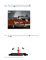
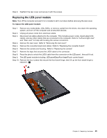
Step 9. Reattach the rear cover and secure it with the screws. Replacing the LED panel module Note: Turn off the computer and wait 3 to 5 minutes to let it cool down before removing the rear cover. To replace the LED panel module: Step 1. Remove any media (disks, CDs, DVDs, or memory cards) from the drives, shut down the operating system, and turn off the computer and all attached devices. Step 2. Unplug all power cords from electrical outlets. Step 3. Disconnect all cables attached to the computer. This includes power cords, input/output (I/O) cables, and any other cables that are connected to the computer. Refer to "Left and right view" and "Rear view" for help with locating the various connectors. Step 4. Remove the rear cover. Refer to "Removing the rear cover". Step 5. Remove the converter board and cables. Refer to "Replacing the converter board". Step 6. Remove the camera and housing. Refer to "Replacing the camera". Step 7. Remove the tape that secures the LVDS cable to the connector. Step 8. Press the pins to unlock the LVDS cable from the connector on the LED panel , then pull it out. Step 9. The LED panel module including: LED panelGlassFront bezelTouch control board Step 10. Remove the four screws that secure the front bezel hinge, then lift up the front bezel hinge to remove it. 1 Chapter 8. Replacing hardware 45
-
 1
1 -
2
-
3
-
4
-
5
-
6
-
7
-
8
-
9
-
10
-
11
-
12
-
13
-
14
-
15
-
16
-
17
-
18
-
19
-
20
-
21
-
22
-
23
-
24
-
25
-
26
-
27
-
28
-
29
-
30
-
31
-
32
-
33
-
34
-
35
-
36
-
37
-
38
-
39
-
40
-
41
-
42
-
43
-
44
-
45
-
 46
46 -
 47
47 -
 48
48 -
 49
49 -
 50
50 -
 51
51 -
 52
52 -
 53
53 -
 54
54 -
 55
55 -
 56
56 -
57
-
58
-
59
-
60
-
61
 |
 |
