Lenovo G500s Hardware Maintenance Manual - Notebook - Page 42
Hard disk drive, 1030 Hard disk driveHDD/Memory/Mini PCI Express Card slot - screws
 |
View all Lenovo G500s manuals
Add to My Manuals
Save this manual to your list of manuals |
Page 42 highlights
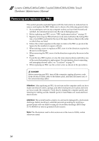
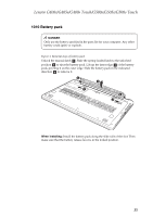
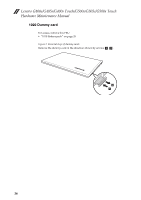
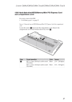
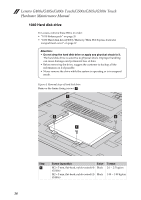
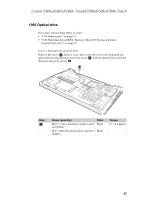
Lenovo G400s/G405s/G400s Touch/G500s/G505s/G500s Touch Hardware Maintenance Manual 1040 Hard disk drive For access, remove these FRUs in order: • "1010 Battery pack" on page 35 • "1030 Hard disk drive(HDD)/Memory/Mini PCI Express Card slot compartment cover" on page 37 Attention: • Do not drop the hard disk drive or apply any physical shock to it. The hard disk drive is sensitive to physical shock. Improper handling can cause damages and permanent loss of data. • Before removing the drive, suggest the customer to backup all the information on it if possible. • Never remove the drive while the system is operating or is in suspend mode. Figure 4. Removal steps of hard disk drive Remove the frame fixing screws a . a a a a Step a Screw (quantity) M2 × 5 mm, flat-head, nylok-coated (4) (G500s) M2 × 5 mm, flat-head, nylok-coated (4) (G400s) Color Black Black Torque 2.0 ~ 2.5 kgfcm 1.89 ~ 1.89 kgfcm 38
-
 1
1 -
2
-
3
-
4
-
5
-
6
-
7
-
8
-
9
-
10
-
11
-
12
-
13
-
14
-
15
-
16
-
17
-
18
-
19
-
20
-
21
-
22
-
23
-
24
-
25
-
26
-
27
-
28
-
29
-
30
-
31
-
32
-
33
-
34
-
35
-
36
-
 37
37 -
 38
38 -
 39
39 -
 40
40 -
 41
41 -
 42
42 -
 43
43 -
 44
44 -
 45
45 -
 46
46 -
 47
47 -
48
-
49
-
50
-
51
-
52
-
53
-
54
-
55
-
56
-
57
-
58
-
59
-
60
-
61
-
62
-
63
-
64
-
65
-
66
-
67
-
68
-
69
-
70
-
71
-
72
-
73
-
74
-
75
-
76
-
77
-
78
-
79
-
80
-
81
-
82
-
83
-
84
-
85
-
86
-
87
-
88
-
89
-
90
-
91
-
92
-
93
-
94
-
95
-
96
-
97
-
98
-
99
-
100
-
101
-
102
-
103
-
104
 |
 |
