Lenovo G505 Hardware Maintenance Manual - Lenovo G400, G500, G405, G505, G410, - Page 69
Removal steps of fan assembly and heat sink assembly continued
 |
View all Lenovo G505 manuals
Add to My Manuals
Save this manual to your list of manuals |
Page 69 highlights
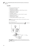
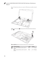
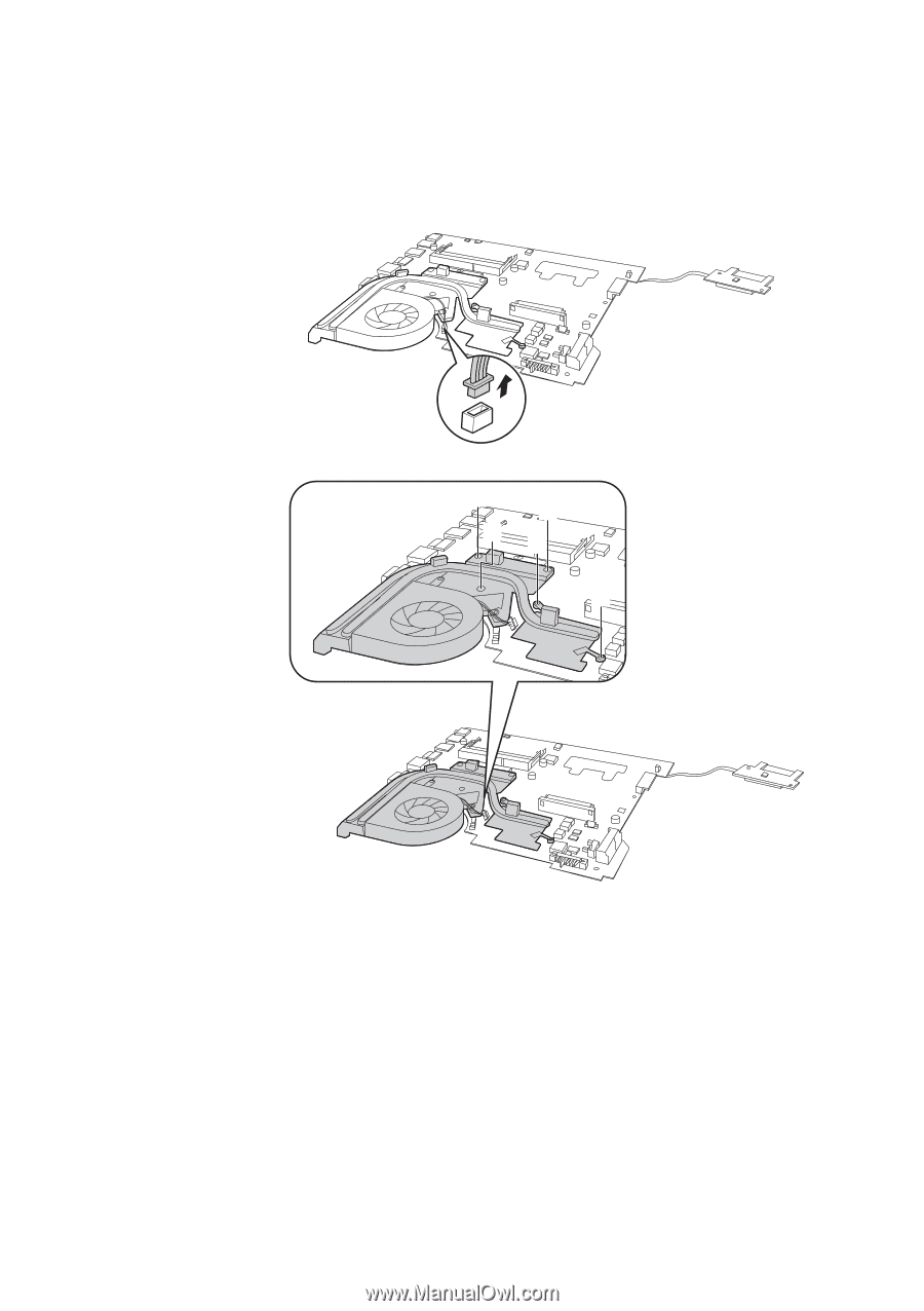
Lenovo G400/G500/G405/G505/G410/G510 Figure 12. Removal steps of fan assembly and heat sink assembly (continued) Detach the fan connector in the direction shown by arrow a loosen three screws b and two screws c to lift the fan assembly. a b b b c c 65
-
 1
1 -
2
-
3
-
4
-
5
-
6
-
7
-
8
-
9
-
10
-
11
-
12
-
13
-
14
-
15
-
16
-
17
-
18
-
19
-
20
-
21
-
22
-
23
-
24
-
25
-
26
-
27
-
28
-
29
-
30
-
31
-
32
-
33
-
34
-
35
-
36
-
37
-
38
-
39
-
40
-
41
-
42
-
43
-
44
-
45
-
46
-
47
-
48
-
49
-
50
-
51
-
52
-
53
-
54
-
55
-
56
-
57
-
58
-
59
-
60
-
61
-
62
-
63
-
 64
64 -
 65
65 -
 66
66 -
 67
67 -
 68
68 -
 69
69 -
 70
70 -
 71
71 -
 72
72 -
 73
73 -
 74
74 -
75
-
76
-
77
-
78
-
79
-
80
-
81
-
82
-
83
-
84
-
85
-
86
-
87
-
88
-
89
-
90
-
91
-
92
-
93
-
94
-
95
-
96
-
97
-
98
-
99
-
100
-
101
-
102
-
103
-
104
-
105
-
106
-
107
-
108
 |
 |
Lenovo G400/G500/G405/G505/G410/G510
65
Figure 12. Removal steps of fan assembly and heat sink assembly (continued)
Detach the fan connector in the direction shown by arrow
loosen three
screws
and two screws
to lift the fan assembly.
a
b
c
a
b
b
c
c
b