Lenovo G505 Hardware Maintenance Manual - Lenovo G400, G500, G405, G505, G410, - Page 80
Integrated camera
 |
View all Lenovo G505 manuals
Add to My Manuals
Save this manual to your list of manuals |
Page 80 highlights
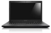
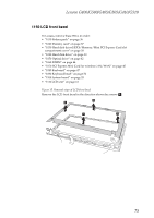
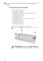
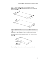
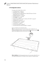
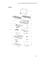
Lenovo G400/G500/G405/G505/G410/G510 Hardware Maintenance Manual 1170 Integrated camera For access, remove these FRUs in order: • "1010 Battery pack" on page 36 • "1020 Dummy card" on page 37 • "1030 Hard disk drive(HDD)/Memory/Mini PCI Express Card slot compartment cover" on page 38 • "1040 Hard disk drive" on page 39 • "1050 Optical drive" on page 42 • "1060 DIMM" on page 44 • "1070 PCI Express Mini Card for wireless LAN/WAN" on page 45 • "1080 Keyboard" on page 47 • "1090 Keyboard bezel" on page 51 • "1100 System board" on page 55 • "1110 LCD unit" on page 61 • "1150 LCD front bezel" on page 73 • "1160 LCD panel, LCD cable and hinges" on page 74 Figure 17. Removal steps of integrated camera Note: The integrated camera is stuck on the top center of the LCD cover. Unplug the integrated camera connector in the direction shown by arrow a. Remove the integrated camera from the LCD cover b. a b When installing: Stick the integrated camera to the top center of the LCD cover and adjust the placement of it to make sure the connector is attached firmly. 76
-
 1
1 -
2
-
3
-
4
-
5
-
6
-
7
-
8
-
9
-
10
-
11
-
12
-
13
-
14
-
15
-
16
-
17
-
18
-
19
-
20
-
21
-
22
-
23
-
24
-
25
-
26
-
27
-
28
-
29
-
30
-
31
-
32
-
33
-
34
-
35
-
36
-
37
-
38
-
39
-
40
-
41
-
42
-
43
-
44
-
45
-
46
-
47
-
48
-
49
-
50
-
51
-
52
-
53
-
54
-
55
-
56
-
57
-
58
-
59
-
60
-
61
-
62
-
63
-
64
-
65
-
66
-
67
-
68
-
69
-
70
-
71
-
72
-
73
-
74
-
 75
75 -
 76
76 -
 77
77 -
 78
78 -
 79
79 -
 80
80 -
 81
81 -
 82
82 -
 83
83 -
 84
84 -
 85
85 -
86
-
87
-
88
-
89
-
90
-
91
-
92
-
93
-
94
-
95
-
96
-
97
-
98
-
99
-
100
-
101
-
102
-
103
-
104
-
105
-
106
-
107
-
108
 |
 |