Lenovo G70-80 Laptop Hardware Maintenance Manual - Lenovo G70-70, G70-80, Z70- - Page 49
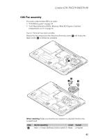
Fan assembly
 |
View all Lenovo G70-80 Laptop manuals
Add to My Manuals
Save this manual to your list of manuals |
Page 49 highlights
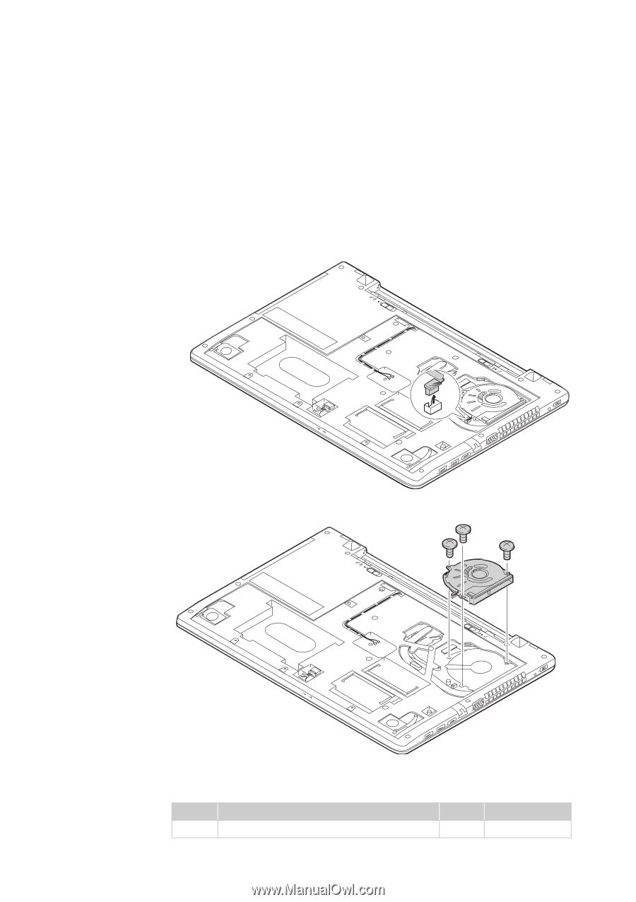
Lenovo G70-70/G70-80/Z70-80 1080 Fan assembly For access, remove these FRUs in order: • "1010 Battery pack" on page 34 • "1030 Hard disk drive(HDD)/Memory/Mini PCI Express Card slot compartment cover" on page 36 Figure 8. Removal steps of fan assembly Detach the fan connector in the direction shown by arrow a and loosen the three screws b to lift the fan assembly. a b b b When installing: Make sure that the fan connector is attached firmly to the system board. Step b Screw (quantity) Color Torque M2.0 × 6.0 mm, flat-head, nylok-coated (3) Black 2.0 kgfcm 45
-
 1
1 -
2
-
3
-
4
-
5
-
6
-
7
-
8
-
9
-
10
-
11
-
12
-
13
-
14
-
15
-
16
-
17
-
18
-
19
-
20
-
21
-
22
-
23
-
24
-
25
-
26
-
27
-
28
-
29
-
30
-
31
-
32
-
33
-
34
-
35
-
36
-
37
-
38
-
39
-
40
-
41
-
42
-
43
-
 44
44 -
 45
45 -
 46
46 -
 47
47 -
 48
48 -
 49
49 -
 50
50 -
 51
51 -
 52
52 -
 53
53 -
 54
54 -
55
-
56
-
57
-
58
-
59
-
60
-
61
-
62
-
63
-
64
-
65
-
66
-
67
-
68
-
69
-
70
-
71
-
72
-
73
-
74
-
75
-
76
-
77
-
78
-
79
-
80
-
81
-
82
-
83
-
84
-
85
-
86
-
87
-
88
-
89
-
90
-
91
-
92
-
93
-
94
-
95
-
96
-
97
-
98
-
99
-
100
-
101
-
102
-
103
-
104
-
105
-
106
-
107
-
108
 |
 |
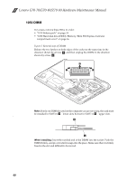
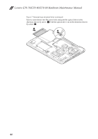
Lenovo G70-70/G70-80/Z70-80
45
1080 Fan assembly
For access, remove these FRUs in order:
•
“1010 Battery pack” on page 34
•
“1030 Hard disk drive(HDD)/Memory/Mini PCI Express Card slot
compartment cover” on page 36
Figure 8. Removal steps of fan assembly
Detach the fan connector in the direction shown by arrow
and loosen the
three screws
to lift the fan assembly.
When installing:
Make sure that the fan connector is attached firmly to the
system board.
Step
Screw (quantity)
Color
Torque
M2.0 × 6.0 mm, flat-head, nylok-coated (3)
Black
2.0 kgfcm
a
b
a
b
b
b
b