Lenovo G710 Hardware Maintenance Manual - Lenovo G700, G710 - Page 44
PCI Express Mini Card for wireless LAN/WAN, Notes, Screw quantity, Color, Torque
 |
View all Lenovo G710 manuals
Add to My Manuals
Save this manual to your list of manuals |
Page 44 highlights
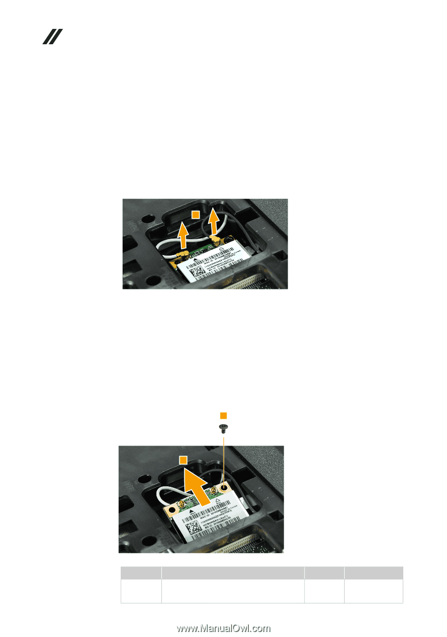
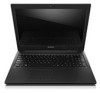
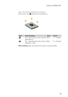
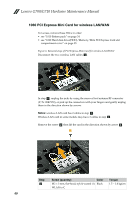
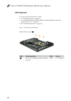
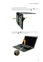
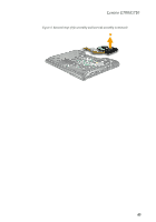
Lenovo G700/G710 Hardware Maintenance Manual 1060 PCI Express Mini Card for wireless LAN/WAN For access, remove these FRUs in order: • see "1010 Battery pack" on page 34 • see "1020 Hard disk drive(HDD)/Memory/Mini PCI Express Card slot compartment cover" on page 35 Figure 6. Removal steps of PCI Express Mini Card for wireless LAN/WAN Disconnect the two wireless LAN cables a. 1 In step a, unplug the jacks by using the removal tool antenna RF connector (P/N: 08K7159), or pick up the connectors with your fingers and gently unplug them in the direction shown by arrows. Notes: wireless LAN card has 2 cables in step a. Wireless LAN card in some models may have 3 cables in step a. Remove the screw b then lift the card in the direction shown by arrow c . 2 3 Step b Screw (quantity) Color M2 × 3 mm, flat-head, nylok-coated (1) Black WLAN to C Torque 1.5 ~ 2.0 kgfcm 40
-
 1
1 -
2
-
3
-
4
-
5
-
6
-
7
-
8
-
9
-
10
-
11
-
12
-
13
-
14
-
15
-
16
-
17
-
18
-
19
-
20
-
21
-
22
-
23
-
24
-
25
-
26
-
27
-
28
-
29
-
30
-
31
-
32
-
33
-
34
-
35
-
36
-
37
-
38
-
 39
39 -
 40
40 -
 41
41 -
 42
42 -
 43
43 -
 44
44 -
 45
45 -
 46
46 -
 47
47 -
 48
48 -
 49
49 -
50
-
51
-
52
-
53
-
54
-
55
-
56
-
57
-
58
-
59
-
60
-
61
-
62
-
63
-
64
-
65
-
66
-
67
-
68
-
69
-
70
-
71
-
72
-
73
-
74
-
75
-
76
-
77
-
78
-
79
-
80
-
81
-
82
-
83
-
84
-
85
-
86
-
87
-
88
 |
 |