Lenovo G710 Hardware Maintenance Manual - Lenovo G700, G710 - Page 51
Removal steps of keyboard bezel continued, Remove three screws - microphone
 |
View all Lenovo G710 manuals
Add to My Manuals
Save this manual to your list of manuals |
Page 51 highlights
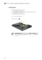
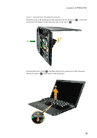
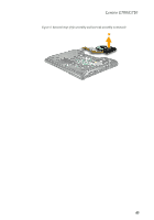
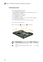
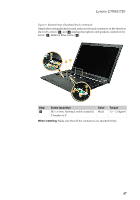
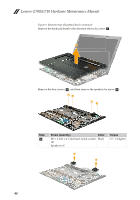
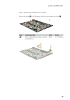
Lenovo G700/G710- Figure 9. Removal steps of keyboard bezel (continued) Detach the touchpad button board and power board connectors in the direction shown by arrows c and d ,unplug microphone and speakers connectors by arrow e . Remove three screws f . 3 4 5 6 6 3 5 4 Step f Screw (quantity) M2 × 6 mm, flat-head, nylok-coated (3) C bracket to C Color Black Torque 1.5 ~ 2.0 kgfcm When installing: Make sure that all the connectors are attached firmly. 47
-
 1
1 -
2
-
3
-
4
-
5
-
6
-
7
-
8
-
9
-
10
-
11
-
12
-
13
-
14
-
15
-
16
-
17
-
18
-
19
-
20
-
21
-
22
-
23
-
24
-
25
-
26
-
27
-
28
-
29
-
30
-
31
-
32
-
33
-
34
-
35
-
36
-
37
-
38
-
39
-
40
-
41
-
42
-
43
-
44
-
45
-
 46
46 -
 47
47 -
 48
48 -
 49
49 -
 50
50 -
 51
51 -
 52
52 -
 53
53 -
 54
54 -
 55
55 -
 56
56 -
57
-
58
-
59
-
60
-
61
-
62
-
63
-
64
-
65
-
66
-
67
-
68
-
69
-
70
-
71
-
72
-
73
-
74
-
75
-
76
-
77
-
78
-
79
-
80
-
81
-
82
-
83
-
84
-
85
-
86
-
87
-
88
 |
 |
Lenovo G700/G710
-
47
Figure 9. Removal steps of keyboard bezel (continued)
Detach the touchpad button board and power board connectors in the direction
shown by arrows
and
,unplug microphone and speakers connectors by
arrow
. Remove three screws
.
When installing:
Make sure that all the connectors are attached firmly.
Step
Screw (quantity)
Color
Torque
M2 × 6 mm, flat-head, nylok-coated (3)
C bracket to C
Black
1.5 ~ 2.0 kgfcm
c
d
e
f
6
6
3
4
5
3
4
5
f