Lenovo H520e Lenovo H520e Hardware Maintenance Manual - Page 83
optical drive in place., drive with the corresponding holes in the drive bay. Then
 |
View all Lenovo H520e manuals
Add to My Manuals
Save this manual to your list of manuals |
Page 83 highlights
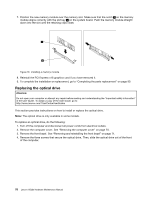
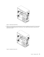
Figure 17. Removing the optical drive 5. Slide the new optical drive into the drive bay from the front and align the screw holes in the new optical drive with the corresponding holes in the drive bay. Then, install the three screws to secure the new optical drive in place. Figure 18. Installing the optical drive Chapter 9. Replacing FRUs 79
-
 1
1 -
2
-
3
-
4
-
5
-
6
-
7
-
8
-
9
-
10
-
11
-
12
-
13
-
14
-
15
-
16
-
17
-
18
-
19
-
20
-
21
-
22
-
23
-
24
-
25
-
26
-
27
-
28
-
29
-
30
-
31
-
32
-
33
-
34
-
35
-
36
-
37
-
38
-
39
-
40
-
41
-
42
-
43
-
44
-
45
-
46
-
47
-
48
-
49
-
50
-
51
-
52
-
53
-
54
-
55
-
56
-
57
-
58
-
59
-
60
-
61
-
62
-
63
-
64
-
65
-
66
-
67
-
68
-
69
-
70
-
71
-
72
-
73
-
74
-
75
-
76
-
77
-
 78
78 -
 79
79 -
 80
80 -
 81
81 -
 82
82 -
 83
83 -
 84
84 -
 85
85 -
 86
86 -
 87
87 -
 88
88 -
89
-
90
-
91
-
92
-
93
-
94
-
95
-
96
-
97
-
98
-
99
-
100
-
101
-
102
-
103
-
104
-
105
-
106
-
107
-
108
-
109
-
110
 |
 |
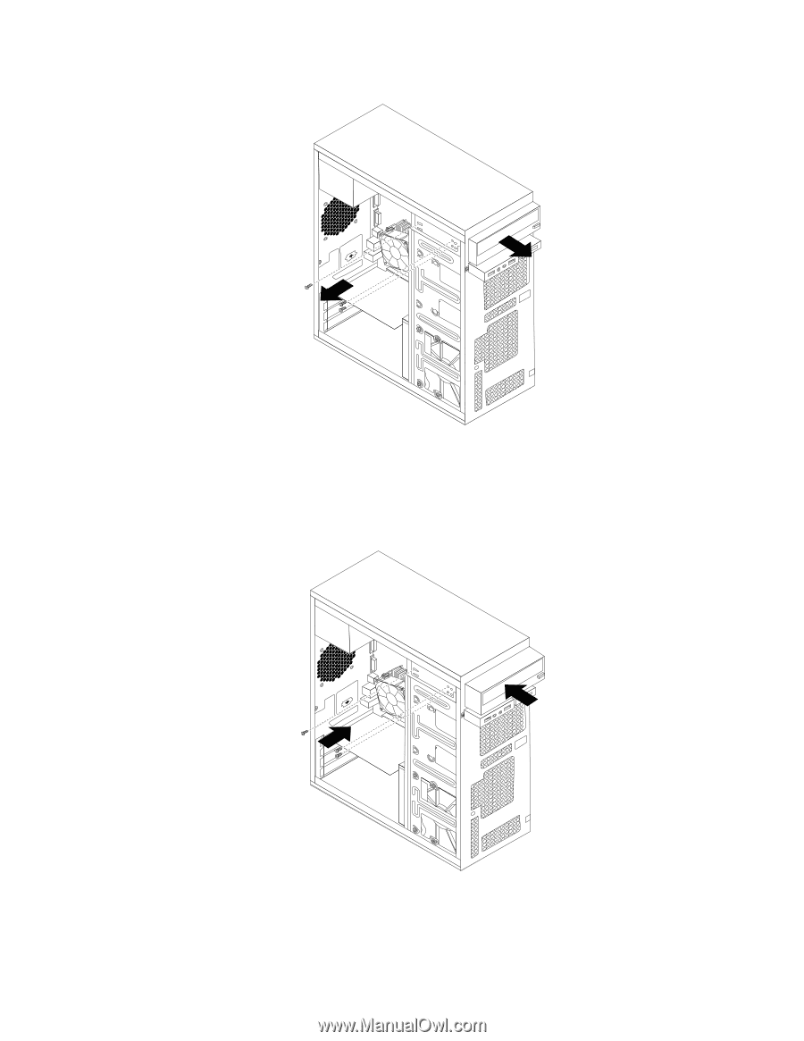
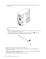
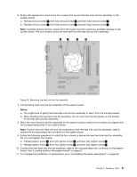
Figure 17. Removing the optical drive
5. Slide the new optical drive into the drive bay from the front and align the screw holes in the new optical
drive with the corresponding holes in the drive bay. Then, install the three screws to secure the new
optical drive in place.
Figure 18. Installing the optical drive
Chapter 9
.
Replacing FRUs
79