Lenovo H520e Lenovo H520e Hardware Maintenance Manual - Page 88
kept as clean as possible.
 |
View all Lenovo H520e manuals
Add to My Manuals
Save this manual to your list of manuals |
Page 88 highlights
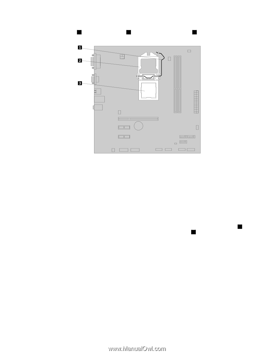
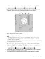
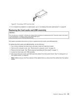
5. Lift the small handle 1 and open the retainer 2 to access the microprocessor 3 . Figure 22. Accessing the microprocessor 6. Lift the microprocessor straight up and out of the microprocessor socket. Figure 23. Removing the microprocessor Notes: a. Your microprocessor and socket might look different from the one illustrated. b. Note the orientation of the microprocessor in the socket. You can either look for the small triangle 1 on one corner of the microprocessor or note the orientation of the notches 2 on the microprocessor. This is important when installing the new microprocessor on the system board. c. Touch only the edges of the microprocessor. Do not touch the gold contacts on the bottom. d. Do not drop anything onto the microprocessor socket while it is exposed. The socket pins must be kept as clean as possible. 7. Make sure that the small handle is in the raised position and the microprocessor retainer is fully open. 8. Remove the protective cover that protects the gold contacts of the new microprocessor. 9. Hold the new microprocessor by its sides and align the small triangle on one corner of the new microprocessor with the corresponding small triangle on one corner of the microprocessor socket. 84 Lenovo H520e Hardware Maintenance Manual
-
 1
1 -
2
-
3
-
4
-
5
-
6
-
7
-
8
-
9
-
10
-
11
-
12
-
13
-
14
-
15
-
16
-
17
-
18
-
19
-
20
-
21
-
22
-
23
-
24
-
25
-
26
-
27
-
28
-
29
-
30
-
31
-
32
-
33
-
34
-
35
-
36
-
37
-
38
-
39
-
40
-
41
-
42
-
43
-
44
-
45
-
46
-
47
-
48
-
49
-
50
-
51
-
52
-
53
-
54
-
55
-
56
-
57
-
58
-
59
-
60
-
61
-
62
-
63
-
64
-
65
-
66
-
67
-
68
-
69
-
70
-
71
-
72
-
73
-
74
-
75
-
76
-
77
-
78
-
79
-
80
-
81
-
82
-
 83
83 -
 84
84 -
 85
85 -
 86
86 -
 87
87 -
 88
88 -
 89
89 -
 90
90 -
 91
91 -
 92
92 -
 93
93 -
94
-
95
-
96
-
97
-
98
-
99
-
100
-
101
-
102
-
103
-
104
-
105
-
106
-
107
-
108
-
109
-
110
 |
 |