Lenovo IdeaCentre K450 Lenovo IdeaCentre K4 Series User Guide - Page 53
Replacing hardware, General information
 |
View all Lenovo IdeaCentre K450 manuals
Add to My Manuals
Save this manual to your list of manuals |
Page 53 highlights
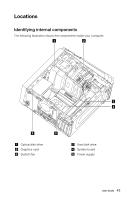
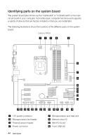
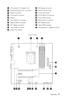
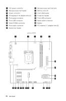
12V power connector Microprocessor and heat sink Memory slots (4) Mini PCI-E slot eSATA connector Solid state disk power connector (Optional) SATA connectors (4) Front panel connector Mode switch connector ROM socket Front USB header Front audio connector System fan header Battery Microprocessor fan header Thermal sensor header Power connector Power fan header LPC debug connector Serial (COM2) connector SPI debug connector Front USB connector (2) Clear CMOS jumper PCI express X 1 adapter slots (3) PCI express X 16 adapter slot Replacing hardware Attention: Do not remove the computer cover or attempt any repair before reading the "Important safety information" in the Safety and Warranty Guide that was included with your computer or in the Hardware Maintenance Manual (HMM) for the computer. To obtain copies of the Safety and Warranty Guide or HMM, go to the Support Web site at http://support.lenovo.com. General information Pre-disassembly instructions Before proceeding with the disassembly procedure, make sure that you do the following: 1. Turn off the power to the system and all peripherals. 2. Unplug all power and signal cables from the computer. 3. Place the system on a flat, stable surface. 48 User Guide
-
 1
1 -
2
-
3
-
4
-
5
-
6
-
7
-
8
-
9
-
10
-
11
-
12
-
13
-
14
-
15
-
16
-
17
-
18
-
19
-
20
-
21
-
22
-
23
-
24
-
25
-
26
-
27
-
28
-
29
-
30
-
31
-
32
-
33
-
34
-
35
-
36
-
37
-
38
-
39
-
40
-
41
-
42
-
43
-
44
-
45
-
46
-
47
-
 48
48 -
 49
49 -
 50
50 -
 51
51 -
 52
52 -
 53
53 -
 54
54 -
 55
55 -
 56
56 -
 57
57 -
 58
58 -
59
-
60
-
61
-
62
-
63
-
64
-
65
-
66
-
67
-
68
-
69
 |
 |
