Lenovo IdeaCentre Q150 Lenovo IdeaCentre Q150 Hardware Maintenance Manual V2.0 - Page 26
Identifying parts on the system board, S/PDIF_OUT connector
 |
View all Lenovo IdeaCentre Q150 manuals
Add to My Manuals
Save this manual to your list of manuals |
Page 26 highlights
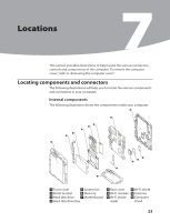
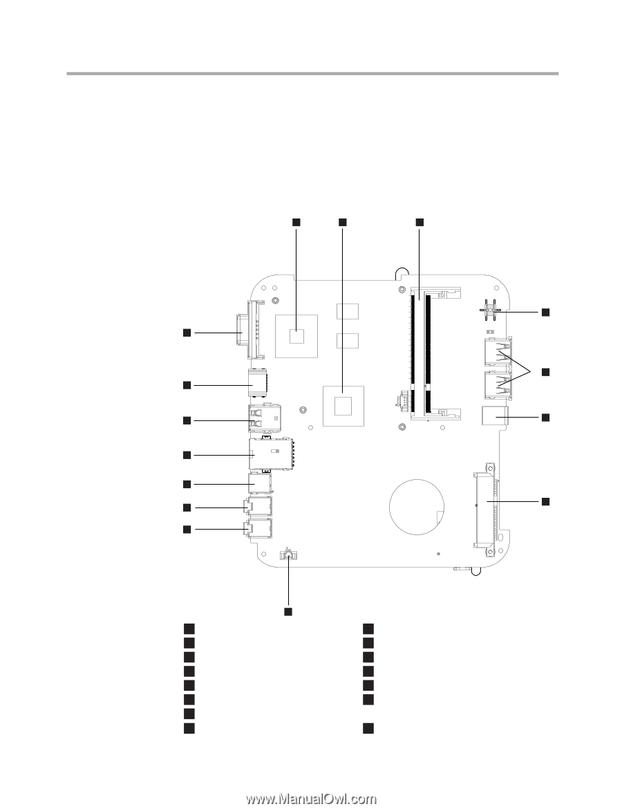
Hardware Maintenance Manual Identifying parts on the system board The system board (sometimes called the planar or motherboard) is the main circuit board in your computer. It provides basic computer functions and supports a variety of devices that are factory-installed or that you can install later. The following illustration shows the locations of parts on the system board. 1 2 3 4 15 5 14 13 6 12 11 7 10 9 8 1 GPU socket 2 CPU socket 3 Memory connector 4 Power switch 5 USB connectors(2) 6 S/PDIF_OUT connector 7 SATA and power socket 8 Battery cable connector 9 Microphone connector 10 Headphone connector 11 Power connector 12 Ethernet connector 13 USB connectors(2) 14 HDMI out connector (Selected models only) 15 VGA connector 24
-
 1
1 -
2
-
3
-
4
-
5
-
6
-
7
-
8
-
9
-
10
-
11
-
12
-
13
-
14
-
15
-
16
-
17
-
18
-
19
-
20
-
 21
21 -
 22
22 -
 23
23 -
 24
24 -
 25
25 -
 26
26 -
 27
27 -
 28
28 -
 29
29 -
 30
30 -
 31
31 -
32
-
33
-
34
-
35
-
36
-
37
-
38
-
39
-
40
-
41
-
42
-
43
-
44
 |
 |
Hardware Maintenance Manual
24
Identifying parts on the system board
The system board (sometimes called the planar or motherboard) is the
main circuit board in your computer. It provides basic computer functions
and supports a variety of devices that are factory-installed or that you can
install later.
The following illustration shows the locations of parts on the system board.
1
2
3
4
5
6
7
8
9
10
11
12
13
15
14
1
GPU socket
9
Microphone connector
2
CPU socket
10
Headphone connector
3
Memory connector
11
Power connector
4
Power switch
12
Ethernet connector
5
USB connectors(2)
13
USB connectors(2)
6
S/PDIF_OUT connector
14
HDMI out connector
7
SATA and power socket
8
Battery cable connector
(Selected models only)
15
VGA connector