Lenovo IdeaPad U330p Hardware Maintenance Manual - Lenovo IdeaPad U330p, U330 - Page 60
Base cover, speakers, USB board, power assembly and power board continued, M2.5 × 3.5 mm
 |
View all Lenovo IdeaPad U330p manuals
Add to My Manuals
Save this manual to your list of manuals |
Page 60 highlights
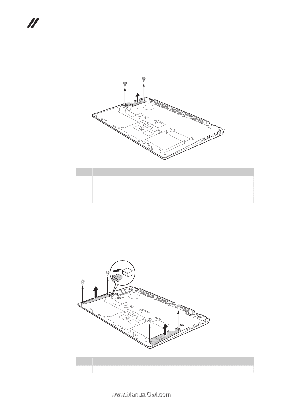
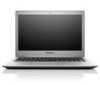
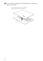
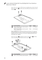
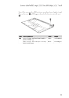
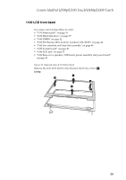
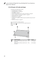
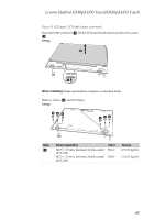
Lenovo IdeaPad U330p/U330 Touch/U430p/U430 Touch Hardware Maintenance Manual Figure 9. Base cover, speakers, USB board, power assembly and power board (continued) Remove two screws b, and then remove the USB board in the direction shown by arrow c. b b c Step a Screw (quantity) M2.5 × 3.5 mm, flat-head, nylok-coated (2) (U330p/U330 Touch) M2.5 × 3.0 mm, flat-head, nylok-coated (2) (U430p/U430 Touch) Color Silver Black Torque 2.5±0.3kgfcm 2.5±0.2 kgfcm When installing: When attaching the USB board to the base cover, adjust the placement of the USB as shown , and make sure that both of the USB jacks are attached to the holes on the base cover as shown. Improper placement of the jacks might cause a damage. Remove four screws a , unplug the connector in the direction b , and then remove the speakers in the direction shown by arrow c . ab a c a a c Step Screw (quantity) a M2.0 × 6.8 mm, flat-head, nylok-coated (4) Color Black Torque 2.0±0.2 kgfcm 56
-
 1
1 -
2
-
3
-
4
-
5
-
6
-
7
-
8
-
9
-
10
-
11
-
12
-
13
-
14
-
15
-
16
-
17
-
18
-
19
-
20
-
21
-
22
-
23
-
24
-
25
-
26
-
27
-
28
-
29
-
30
-
31
-
32
-
33
-
34
-
35
-
36
-
37
-
38
-
39
-
40
-
41
-
42
-
43
-
44
-
45
-
46
-
47
-
48
-
49
-
50
-
51
-
52
-
53
-
54
-
 55
55 -
 56
56 -
 57
57 -
 58
58 -
 59
59 -
 60
60 -
 61
61 -
 62
62 -
 63
63 -
 64
64 -
 65
65 -
66
-
67
-
68
-
69
-
70
-
71
-
72
-
73
-
74
-
75
-
76
-
77
-
78
-
79
-
80
-
81
-
82
-
83
-
84
-
85
-
86
-
87
-
88
-
89
-
90
-
91
 |
 |