Lenovo IdeaPad U330p Hardware Maintenance Manual - Lenovo IdeaPad U330p, U330 - Page 66
Integrated camera
 |
View all Lenovo IdeaPad U330p manuals
Add to My Manuals
Save this manual to your list of manuals |
Page 66 highlights
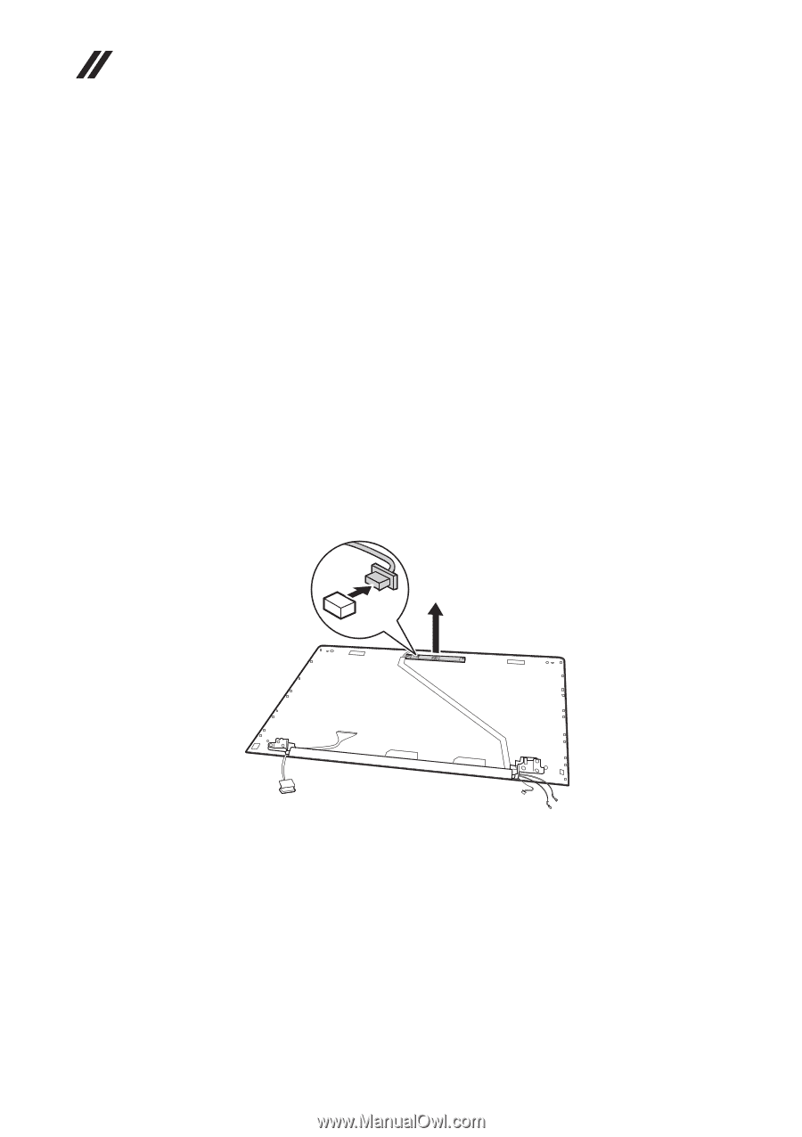
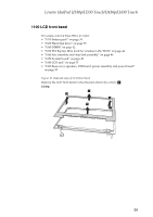
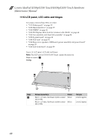
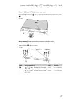
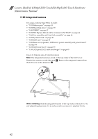
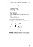
Lenovo IdeaPad U330p/U330 Touch/U430p/U430 Touch Hardware Maintenance Manual 1120 Integrated camera For access, remove these FRUs in order: • "1010 Battery pack" on page 34 • "1030 Hard disk drive" on page 39 • "1040 DIMM" on page 42 • "1050 PCI Express Mini Card for wireless LAN/WAN" on page 44 • "1060 Fan assembly and Heat Sink assembly" on page 46 • "1070 System board" on page 49 • "1080 LCD unit" on page 53 • "1090 Base cover, speakers, USB board, power assembly and power board" on page 55 • "1100 LCD front bezel" on page 59 • "1110 LCD panel, LCD cable and hinges" on page 60 Figure 12. Removal steps of integrated camera Note: The integrated camera is stuck on the top center of the LCD cover. Detach the connector in the direction a, Remove the integrated camera from the LCD cover in the direction b. a b When installing: Stick the integrated camera to the top center of the LCD cover and adjust the placement of it to make sure the connector is attached firmly. 62
-
 1
1 -
2
-
3
-
4
-
5
-
6
-
7
-
8
-
9
-
10
-
11
-
12
-
13
-
14
-
15
-
16
-
17
-
18
-
19
-
20
-
21
-
22
-
23
-
24
-
25
-
26
-
27
-
28
-
29
-
30
-
31
-
32
-
33
-
34
-
35
-
36
-
37
-
38
-
39
-
40
-
41
-
42
-
43
-
44
-
45
-
46
-
47
-
48
-
49
-
50
-
51
-
52
-
53
-
54
-
55
-
56
-
57
-
58
-
59
-
60
-
 61
61 -
 62
62 -
 63
63 -
 64
64 -
 65
65 -
 66
66 -
 67
67 -
 68
68 -
 69
69 -
 70
70 -
 71
71 -
72
-
73
-
74
-
75
-
76
-
77
-
78
-
79
-
80
-
81
-
82
-
83
-
84
-
85
-
86
-
87
-
88
-
89
-
90
-
91
 |
 |