Lenovo IdeaPad Y560 Lenovo IdeaPad Y560 Hardware Maintenance Manual V2.0 - Page 77
LCD front bezel
 |
View all Lenovo IdeaPad Y560 manuals
Add to My Manuals
Save this manual to your list of manuals |
Page 77 highlights
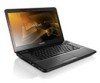
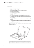
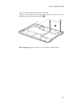
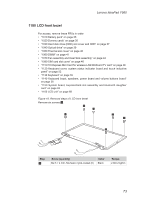
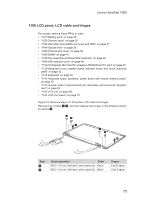
Lenovo IdeaPad Y560 1180 LCD front bezel For access, remove these FRUs in order: •• "1010 Battery pack" on page 35 •• "1020 Dummy cards" on page 36 •• "1030 Hard disk drive (HDD) slot cover and HDD" on page 37 •• "1040 Optical drive" on page 39 •• "1050 Thermal slot cover" on page 40 •• "1060 DIMM" on page 41 •• "1070 Fan assembly and Heat Sink assembly" on page 42 •• "1090 SIM card slot cover" on page 46 •• "1110 PCI Express Mini Card for wireless LAN/WAN and TV card" on page 48 •• "1120 Keyboard cover, system status indicator board and touch inductive panel" on page 52 •• "1130 Keyboard" on page 55 •• "1140 Keyboard bezel, speakers, power board and volume buttons board" on page 56 •• "1150 System board, ExpressCard slot assembly and bluetooth daughter card" on page 63 •• "1160 LCD unit" on page 68 Figure 18. Removal steps of LCD front bezel Remove six screws 1. 1 1 1 1 1 1 Step 1 Screw (quantity) M2.5 × 4 mm, flat-head, nylok-coated (6) Color Black Torque 2.0±0.2 kgfcm 73
-
 1
1 -
2
-
3
-
4
-
5
-
6
-
7
-
8
-
9
-
10
-
11
-
12
-
13
-
14
-
15
-
16
-
17
-
18
-
19
-
20
-
21
-
22
-
23
-
24
-
25
-
26
-
27
-
28
-
29
-
30
-
31
-
32
-
33
-
34
-
35
-
36
-
37
-
38
-
39
-
40
-
41
-
42
-
43
-
44
-
45
-
46
-
47
-
48
-
49
-
50
-
51
-
52
-
53
-
54
-
55
-
56
-
57
-
58
-
59
-
60
-
61
-
62
-
63
-
64
-
65
-
66
-
67
-
68
-
69
-
70
-
71
-
 72
72 -
 73
73 -
 74
74 -
 75
75 -
 76
76 -
 77
77 -
 78
78 -
 79
79 -
 80
80 -
 81
81 -
 82
82 -
83
-
84
-
85
-
86
-
87
-
88
-
89
-
90
-
91
-
92
-
93
-
94
-
95
-
96
-
97
-
98
-
99
-
100
-
101
-
102
-
103
 |
 |
