Lenovo J105 Hardware Maintenance Manual - Page 105
Replacing, microprocessor, Types
 |
View all Lenovo J105 manuals
Add to My Manuals
Save this manual to your list of manuals |
Page 105 highlights
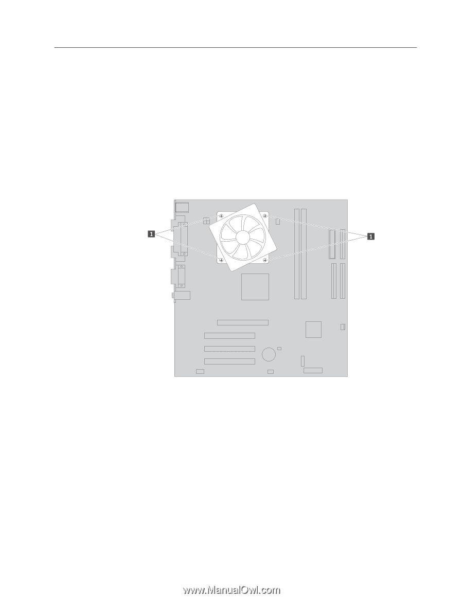
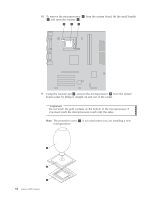
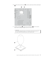
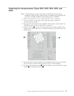
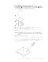
Replacing the microprocessor (Types 8252, 8253, 8254, 8255, and 8256) Note: A thermal grease syringe is required to complete the microprocessor installation. Make sure the grease syringe is available before beginning the procedure. The FRU number for the thermal grease is 91P8835. 1. Remove the left-side cover. See "Removing the covers" on page 82. 2. Lay the computer on the right side to make the system board and microprocessor accessible. 3. Disconnect the heat sink and fan assembly cable from the system board. See "Identifying parts on the system board" on page 85. 4. Remove the four 1 screws securing the heat sink and fan assembly to the system board. Notice that there is a retention bracket on the back side of the system board. 5. Lift the heat sink and fan assembly off the failing system board. Lay the heat sink on its side so that the thermal grease does not touch anything. 6. To remove the microprocessor 2 from the failing system board, lift the small handle 3 and open the retainer 1 . Chapter 8. Replacing FRUs (Types 8252, 8253, 8254, 8255, 8256, 8257, 8258, and 8259) 99
-
 1
1 -
2
-
3
-
4
-
5
-
6
-
7
-
8
-
9
-
10
-
11
-
12
-
13
-
14
-
15
-
16
-
17
-
18
-
19
-
20
-
21
-
22
-
23
-
24
-
25
-
26
-
27
-
28
-
29
-
30
-
31
-
32
-
33
-
34
-
35
-
36
-
37
-
38
-
39
-
40
-
41
-
42
-
43
-
44
-
45
-
46
-
47
-
48
-
49
-
50
-
51
-
52
-
53
-
54
-
55
-
56
-
57
-
58
-
59
-
60
-
61
-
62
-
63
-
64
-
65
-
66
-
67
-
68
-
69
-
70
-
71
-
72
-
73
-
74
-
75
-
76
-
77
-
78
-
79
-
80
-
81
-
82
-
83
-
84
-
85
-
86
-
87
-
88
-
89
-
90
-
91
-
92
-
93
-
94
-
95
-
96
-
97
-
98
-
99
-
 100
100 -
 101
101 -
 102
102 -
 103
103 -
 104
104 -
 105
105 -
 106
106 -
 107
107 -
 108
108 -
 109
109 -
 110
110 -
111
-
112
-
113
-
114
-
115
-
116
-
117
-
118
-
119
-
120
-
121
-
122
-
123
-
124
-
125
-
126
-
127
-
128
-
129
-
130
-
131
-
132
-
133
-
134
-
135
-
136
-
137
-
138
-
139
-
140
-
141
-
142
-
143
-
144
-
145
-
146
-
147
-
148
-
149
-
150
-
151
-
152
-
153
-
154
-
155
-
156
-
157
-
158
-
159
-
160
-
161
-
162
-
163
-
164
-
165
-
166
-
167
-
168
-
169
-
170
-
171
-
172
-
173
-
174
-
175
-
176
-
177
-
178
-
179
-
180
-
181
-
182
-
183
-
184
-
185
-
186
-
187
-
188
-
189
-
190
-
191
-
192
-
193
-
194
-
195
-
196
-
197
-
198
-
199
-
200
-
201
-
202
-
203
-
204
-
205
-
206
-
207
-
208
-
209
-
210
-
211
-
212
-
213
-
214
-
215
-
216
-
217
-
218
 |
 |