Lenovo K4450 Hardware Maintenance Manual - Lenovo K4450 and K4450A - Page 56
Removal steps of the memory modules, When installing, andthencarefullyremovethe, memorymodule
 |
View all Lenovo K4450 manuals
Add to My Manuals
Save this manual to your list of manuals |
Page 56 highlights
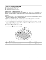
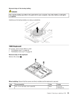
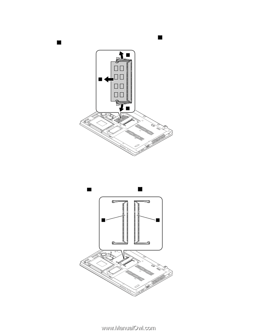
Removal steps of the memory modules Release the two latches on both edges of the socket at the same time 1 , and then carefully remove the memory module 2 . 1 2 1 When installing: Insert the notched end of the memory module into the memory slot at an angle of about 20 degrees. Press the memory module firmly, and pivot it downward until it snaps into place. Ensure that the memory module is firmly installed in the slot and does not move easily. Note: If only one memory module is to be installed into the computer you are servicing, the memory module must be installed in SLOT-0 (slot a ), but not in SLOT-1 (slot b ). a b 50 Hardware Maintenance Manual
-
 1
1 -
2
-
3
-
4
-
5
-
6
-
7
-
8
-
9
-
10
-
11
-
12
-
13
-
14
-
15
-
16
-
17
-
18
-
19
-
20
-
21
-
22
-
23
-
24
-
25
-
26
-
27
-
28
-
29
-
30
-
31
-
32
-
33
-
34
-
35
-
36
-
37
-
38
-
39
-
40
-
41
-
42
-
43
-
44
-
45
-
46
-
47
-
48
-
49
-
50
-
 51
51 -
 52
52 -
 53
53 -
 54
54 -
 55
55 -
 56
56 -
 57
57 -
 58
58 -
 59
59 -
 60
60 -
 61
61 -
62
-
63
-
64
-
65
-
66
-
67
-
68
-
69
-
70
-
71
-
72
-
73
-
74
-
75
-
76
-
77
-
78
-
79
-
80
-
81
-
82
-
83
-
84
-
85
-
86
-
87
-
88
 |
 |
Removal steps of the memory modules
Releasethetwolatchesonbothedgesofthesocketatthesametime
1
,andthencarefullyremovethe
memorymodule
2
.
2
1
1
When installing:
Insertthenotchedendofthememorymoduleintothememoryslotatanangleofabout20
degrees.Pressthememorymodulefirmly,andpivotitdownwarduntilitsnapsintoplace.Ensurethatthe
memorymoduleisfirmlyinstalledintheslotanddoesnotmoveeasily.
Note:
Ifonlyonememorymoduleistobeinstalledintothecomputeryouareservicing,thememorymodule
mustbeinstalledinSLOT-0(slot
a
),butnotinSLOT-1(slot
b
).
a
b
50
HardwareMaintenanceManual