Lenovo PC 300PL Technical Information Manual 6562, 6592 - Page 59
Serial Port Connectors, Infrared Port Connector Optional
 |
View all Lenovo PC 300PL manuals
Add to My Manuals
Save this manual to your list of manuals |
Page 59 highlights
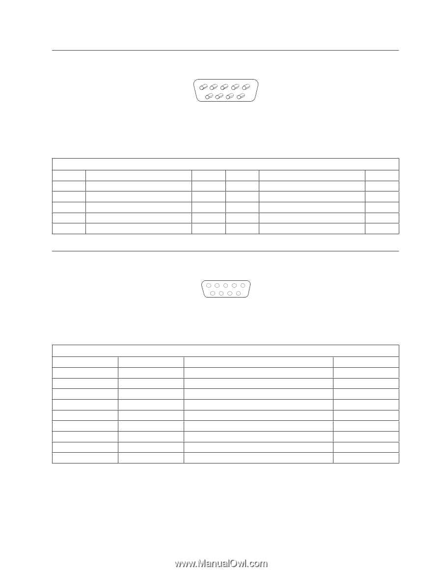
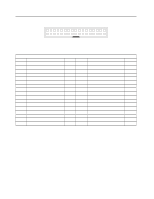
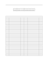
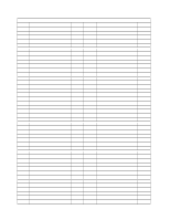
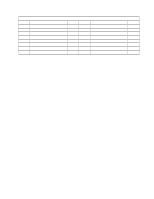
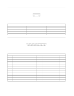
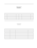
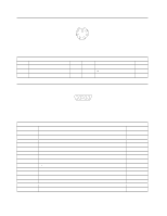
Appendix A. Connector Pin Assignments Serial Port Connectors 1 5 Figure 11. Serial Port Connector 6 9 The external interface for the serial ports consists of two, 9-pin, male, D-shell connectors (in a stacked configuration). Table 46. Pin Assignments for the Serial Port Connectors Pin Signal Name I/O Pin Signal Name I/O 1 Data carrier detect I 2 Receive data# I 3 Transmit data# O 4 Data terminal read O 5 Ground NA 6 Data set ready I 7 Request to send O 8 Clear to send I 9 Ring indicator I Infrared Port Connector (Optional) 1 5 Figure 12. Infrared Port Connector 6 9 The external interface for the optional infrared port is a 9-pin, female, D-shell connector. Table 47. Pin Assignments for the Infrared Connector Pin Signal Name Signal Definition I/O 1 IRTX Infrared transmitted data (output) O 2 Ground NA 3 Reserved NA 4 IRSL2 Infrared module select 2 O 5 IRSL1 Infrared module select 1 O 6 IRRX Infrared received data (input) I 7 VCC Input voltage (5 V) from system board NA 8 IRSL0 Infrared module select 0 O 9 NC No connect NA Appendix A. Connector Pin Assignments 47
-
 1
1 -
2
-
3
-
4
-
5
-
6
-
7
-
8
-
9
-
10
-
11
-
12
-
13
-
14
-
15
-
16
-
17
-
18
-
19
-
20
-
21
-
22
-
23
-
24
-
25
-
26
-
27
-
28
-
29
-
30
-
31
-
32
-
33
-
34
-
35
-
36
-
37
-
38
-
39
-
40
-
41
-
42
-
43
-
44
-
45
-
46
-
47
-
48
-
49
-
50
-
51
-
52
-
53
-
 54
54 -
 55
55 -
 56
56 -
 57
57 -
 58
58 -
 59
59 -
 60
60 -
 61
61 -
 62
62 -
 63
63 -
 64
64 -
65
-
66
-
67
-
68
-
69
-
70
-
71
-
72
-
73
-
74
-
75
-
76
-
77
-
78
 |
 |