Lenovo ThinkCentre Edge 92 Hardware Maintenance Manual (HMM) (July 2012) - Thi - Page 151
The failing system board must be returned with a microprocessor socket cover to protect the pins during
 |
View all Lenovo ThinkCentre Edge 92 manuals
Add to My Manuals
Save this manual to your list of manuals |
Page 151 highlights
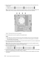
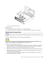
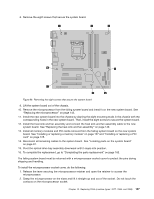
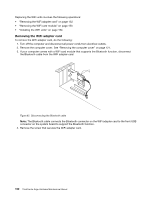
8. Remove the eight screws that secure the system board. Figure 86. Removing the eight screws that secure the system board 9. Lift the system board out of the chassis. 10. Remove the microprocessor from the failing system board and install it on the new system board. See "Replacing the microprocessor" on page 143. 11. Install the new system board into the chassis by aligning the eight mounting studs in the chassis with the corresponding holes in the new system board. Then, install the eight screws to secure the system board. 12. Install the heat sink and fan assembly and connect the heat sink and fan assembly cable to the new system board. See "Replacing the heat sink and fan assembly" on page 140. 13. Install all memory modules and PCI cards removed from the failing system board on the new system board. See "Installing or replacing a memory module" on page 127 and "Installing or replacing a PCI card" on page 125. 14. Reconnect all remaining cables to the system board. See "Locating parts on the system board" on page 81. 15. Pivot the optical drive bay assembly downward until it snaps into position. 16. To complete the replacement, go to "Completing the parts replacement" on page 160. The failing system board must be returned with a microprocessor socket cover to protect the pins during shipping and handling. To install the microprocessor socket cover, do the following: 1. Release the lever securing the microprocessor retainer and open the retainer to access the microprocessor. 2. Grasp the microprocessor on the sides and lift it straight up and out of the socket. Do not touch the contacts on the microprocessor socket. Chapter 10. Replacing FRUs (machine types: 3377, 3386, and 3388) 147
-
 1
1 -
2
-
3
-
4
-
5
-
6
-
7
-
8
-
9
-
10
-
11
-
12
-
13
-
14
-
15
-
16
-
17
-
18
-
19
-
20
-
21
-
22
-
23
-
24
-
25
-
26
-
27
-
28
-
29
-
30
-
31
-
32
-
33
-
34
-
35
-
36
-
37
-
38
-
39
-
40
-
41
-
42
-
43
-
44
-
45
-
46
-
47
-
48
-
49
-
50
-
51
-
52
-
53
-
54
-
55
-
56
-
57
-
58
-
59
-
60
-
61
-
62
-
63
-
64
-
65
-
66
-
67
-
68
-
69
-
70
-
71
-
72
-
73
-
74
-
75
-
76
-
77
-
78
-
79
-
80
-
81
-
82
-
83
-
84
-
85
-
86
-
87
-
88
-
89
-
90
-
91
-
92
-
93
-
94
-
95
-
96
-
97
-
98
-
99
-
100
-
101
-
102
-
103
-
104
-
105
-
106
-
107
-
108
-
109
-
110
-
111
-
112
-
113
-
114
-
115
-
116
-
117
-
118
-
119
-
120
-
121
-
122
-
123
-
124
-
125
-
126
-
127
-
128
-
129
-
130
-
131
-
132
-
133
-
134
-
135
-
136
-
137
-
138
-
139
-
140
-
141
-
142
-
143
-
144
-
145
-
 146
146 -
 147
147 -
 148
148 -
 149
149 -
 150
150 -
 151
151 -
 152
152 -
 153
153 -
 154
154 -
 155
155 -
 156
156 -
157
-
158
-
159
-
160
-
161
-
162
-
163
-
164
-
165
-
166
-
167
-
168
-
169
-
170
-
171
-
172
-
173
-
174
-
175
-
176
 |
 |