Lenovo ThinkCentre Edge 92z Hardware Maintenance Manual (HMM) (June 2012) - Th - Page 97
on it with the alignment keys in the, microprocessor socket, or align the small triangle
 |
View all Lenovo ThinkCentre Edge 92z manuals
Add to My Manuals
Save this manual to your list of manuals |
Page 97 highlights
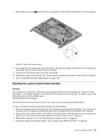
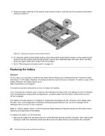
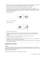
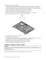
Figure 30. Noting the orientation of the microprocessor in the socket c. Touch only the sides of the microprocessor. Do not touch the gold contacts on the bottom. d. Do not drop anything onto the microprocessor socket while it is exposed. The socket pins must be kept as clean as possible. Figure 31. Removing the microprocessor 9. Make sure that the small handle is in the raised position and the microprocessor retainer is fully open. 10. Hold the new microprocessor and align the notches 2 on it with the alignment keys in the microprocessor socket, or align the small triangle 1 on one corner of the new microprocessor with the corresponding beveled corner of the microprocessor socket. Chapter 9. Replacing FRUs 91
-
 1
1 -
2
-
3
-
4
-
5
-
6
-
7
-
8
-
9
-
10
-
11
-
12
-
13
-
14
-
15
-
16
-
17
-
18
-
19
-
20
-
21
-
22
-
23
-
24
-
25
-
26
-
27
-
28
-
29
-
30
-
31
-
32
-
33
-
34
-
35
-
36
-
37
-
38
-
39
-
40
-
41
-
42
-
43
-
44
-
45
-
46
-
47
-
48
-
49
-
50
-
51
-
52
-
53
-
54
-
55
-
56
-
57
-
58
-
59
-
60
-
61
-
62
-
63
-
64
-
65
-
66
-
67
-
68
-
69
-
70
-
71
-
72
-
73
-
74
-
75
-
76
-
77
-
78
-
79
-
80
-
81
-
82
-
83
-
84
-
85
-
86
-
87
-
88
-
89
-
90
-
91
-
 92
92 -
 93
93 -
 94
94 -
 95
95 -
 96
96 -
 97
97 -
 98
98 -
 99
99 -
 100
100 -
 101
101 -
 102
102 -
103
-
104
-
105
-
106
-
107
-
108
-
109
-
110
-
111
-
112
-
113
-
114
-
115
-
116
-
117
-
118
-
119
-
120
-
121
-
122
-
123
-
124
-
125
-
126
 |
 |
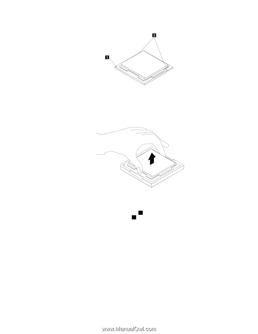
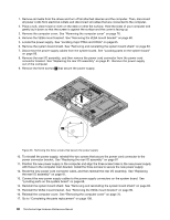
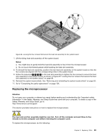
Figure 30. Noting the orientation of the microprocessor in the socket
c.
Touch only the sides of the microprocessor. Do not touch the gold contacts on the bottom.
d. Do not drop anything onto the microprocessor socket while it is exposed. The socket pins must be
kept as clean as possible.
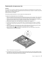
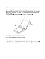
Figure 31. Removing the microprocessor
9. Make sure that the small handle is in the raised position and the microprocessor retainer is fully open.
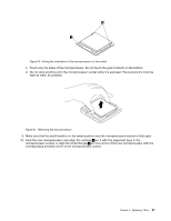
10. Hold the new microprocessor and align the notches
2
on it with the alignment keys in the
microprocessor socket, or align the small triangle
1
on one corner of the new microprocessor with the
corresponding beveled corner of the microprocessor socket.
Chapter 9
.
Replacing FRUs
91