Lenovo ThinkCentre M55p User Manual - Page 50
Replacing, cover, connecting, cables
 |
View all Lenovo ThinkCentre M55p manuals
Add to My Manuals
Save this manual to your list of manuals |
Page 50 highlights
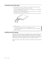
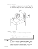
3. Locate the Clear CMOS/Recovery jumper on the system board. See "Identifying parts on the system board" on page 23. 4. Move the jumper from the standard position (pins 1 and 2) to the maintenance or configure position (pins 2 and 3). Note: If the system board has only two pins for clearing CMOS, add a jumper to the two pins. 5. Replace the cover and connect the power cord. See "Replacing the cover and connecting the cables." 6. Restart the computer, leave it on for approximately ten seconds. Turn off the computer by holding the power switch for approximately five seconds. The computer will turn off. 7. Repeat steps 2 through 4 on page 33. 8. Move the jumper back to the standard (pins 1 and 2). Note: If your system board has only two pins for clearing CMOS, just remove the jumper from the two pins. 9. Replace the cover and connect the power cord. See "Replacing the cover and connecting the cables." Replacing the cover and connecting the cables After working with options, you need to install any removed parts, replace the cover, and reconnect any cables, including telephone lines and power cords. Also, depending on the option that is installed, you might need to confirm the updated information in the Setup Utility program. To replace the cover and connect cables to your computer: 1. Ensure that all components have been reassembled correctly and that no tools or loose screws are left inside your computer. 2. If the hard disk drive bracket was removed, reinstall the bracket. See "Removing the hard disk drive mounting bracket" on page 21. 3. Clear any cables that might impede the replacement of the cover. 4. Position the cover on the chassis so that the rail guides on the bottom of the cover engage the rails and push the cover closed until it latches. 34 User Guide 5. Install any cover locking devices such as a cable lock or padlock as necessary.
-
 1
1 -
2
-
3
-
4
-
5
-
6
-
7
-
8
-
9
-
10
-
11
-
12
-
13
-
14
-
15
-
16
-
17
-
18
-
19
-
20
-
21
-
22
-
23
-
24
-
25
-
26
-
27
-
28
-
29
-
30
-
31
-
32
-
33
-
34
-
35
-
36
-
37
-
38
-
39
-
40
-
41
-
42
-
43
-
44
-
 45
45 -
 46
46 -
 47
47 -
 48
48 -
 49
49 -
 50
50 -
 51
51 -
 52
52 -
 53
53 -
 54
54 -
 55
55 -
56
-
57
-
58
-
59
-
60
-
61
-
62
-
63
-
64
-
65
-
66
-
67
-
68
-
69
-
70
-
71
-
72
-
73
-
74
-
75
-
76
-
77
-
78
-
79
-
80
-
81
-
82
-
83
-
84
-
85
-
86
-
87
-
88
-
89
-
90
 |
 |