Lenovo ThinkCentre M70e Hardware Maintenance Manual (HMM) for ThinkCentre M70e - Page 100
Replacing the rear fan assembly, Removing the front audio and USB assembly
 |
View all Lenovo ThinkCentre M70e manuals
Add to My Manuals
Save this manual to your list of manuals |
Page 100 highlights
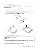
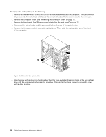
1. Remove all media from the drives and turn off all attached devices and the computer. Then, disconnect all power cords from electrical outlets and disconnect all cables that are connected to the computer. 2. Remove the computer cover. See "Removing the computer cover" on page 71. 3. Remove the front bezel. See "Removing and reinstalling the front bezel" on page 72. 4. Disconnect the front audio and USB assembly cables from the system board. See "Locating parts on the system board" on page 69. 5. Note the front audio and USB assembly cable routing and remove the screw that secures the front audio and USB assembly. Then, remove the front audio and USB assembly from the chassis. Figure 31. Removing the front audio and USB assembly 6. Route the cables of the new front audio and USB assembly through the hole in the chassis. 7. Position the new front audio and USB assembly to the chassis so that the screw hole in the new front audio and USB assembly is aligned with the corresponding hole in the chassis. 8. Install the screw to secure the new front audio and USB assembly in place. 9. Connect the new front audio and USB assembly cables to the system board. See "Locating parts on the system board" on page 69. 10. Reinstall the front bezel. See "Removing and reinstalling the front bezel" on page 72. 11. To complete the replacement, go to "Completing the parts replacement" on page 94. Replacing the rear fan assembly Attention Do not open your computer or attempt any repair before reading and understanding the "Important safety information" in the ThinkCentre Safety and Warranty Guide that came with your computer. To obtain a copy of the ThinkCentre Safety and Warranty Guide, go to: http://www.lenovo.com/support This section provides instructions on how to replace the rear fan assembly. To replace the rear fan assembly, do the following: 92 ThinkCentre Hardware Maintenance Manual
-
 1
1 -
2
-
3
-
4
-
5
-
6
-
7
-
8
-
9
-
10
-
11
-
12
-
13
-
14
-
15
-
16
-
17
-
18
-
19
-
20
-
21
-
22
-
23
-
24
-
25
-
26
-
27
-
28
-
29
-
30
-
31
-
32
-
33
-
34
-
35
-
36
-
37
-
38
-
39
-
40
-
41
-
42
-
43
-
44
-
45
-
46
-
47
-
48
-
49
-
50
-
51
-
52
-
53
-
54
-
55
-
56
-
57
-
58
-
59
-
60
-
61
-
62
-
63
-
64
-
65
-
66
-
67
-
68
-
69
-
70
-
71
-
72
-
73
-
74
-
75
-
76
-
77
-
78
-
79
-
80
-
81
-
82
-
83
-
84
-
85
-
86
-
87
-
88
-
89
-
90
-
91
-
92
-
93
-
94
-
 95
95 -
 96
96 -
 97
97 -
 98
98 -
 99
99 -
 100
100 -
 101
101 -
 102
102 -
 103
103 -
 104
104 -
 105
105 -
106
-
107
-
108
-
109
-
110
-
111
-
112
-
113
-
114
-
115
-
116
-
117
-
118
-
119
-
120
-
121
-
122
-
123
-
124
-
125
-
126
-
127
-
128
-
129
-
130
-
131
-
132
-
133
-
134
-
135
-
136
-
137
-
138
-
139
-
140
-
141
-
142
-
143
-
144
-
145
-
146
-
147
-
148
-
149
-
150
-
151
-
152
-
153
-
154
-
155
-
156
-
157
-
158
-
159
-
160
-
161
-
162
-
163
-
164
-
165
-
166
-
167
-
168
-
169
-
170
-
171
-
172
-
173
-
174
-
175
-
176
-
177
-
178
-
179
-
180
-
181
-
182
-
183
-
184
-
185
-
186
-
187
-
188
-
189
-
190
-
191
-
192
-
193
-
194
-
195
-
196
-
197
-
198
-
199
-
200
-
201
-
202
-
203
-
204
-
205
-
206
-
207
-
208
-
209
-
210
-
211
-
212
-
213
-
214
-
215
-
216
-
217
-
218
-
219
-
220
-
221
-
222
-
223
-
224
-
225
-
226
-
227
-
228
-
229
-
230
-
231
-
232
-
233
-
234
-
235
-
236
-
237
-
238
-
239
-
240
-
241
-
242
-
243
-
244
-
245
-
246
-
247
-
248
-
249
-
250
-
251
-
252
-
253
-
254
-
255
-
256
-
257
-
258
-
259
-
260
-
261
-
262
-
263
-
264
-
265
-
266
-
267
-
268
-
269
-
270
-
271
-
272
-
273
-
274
-
275
-
276
-
277
-
278
-
279
-
280
-
281
-
282
-
283
-
284
-
285
-
286
-
287
-
288
-
289
-
290
-
291
-
292
-
293
-
294
-
295
-
296
-
297
-
298
-
299
-
300
-
301
-
302
-
303
-
304
-
305
-
306
-
307
-
308
-
309
-
310
-
311
-
312
-
313
-
314
-
315
-
316
-
317
-
318
-
319
-
320
-
321
-
322
-
323
-
324
-
325
-
326
-
327
-
328
-
329
-
330
-
331
-
332
-
333
-
334
-
335
-
336
-
337
-
338
-
339
-
340
-
341
-
342
-
343
-
344
-
345
-
346
-
347
-
348
-
349
-
350
-
351
-
352
-
353
-
354
-
355
-
356
-
357
-
358
-
359
-
360
-
361
-
362
-
363
-
364
-
365
-
366
-
367
-
368
-
369
-
370
-
371
-
372
-
373
-
374
-
375
-
376
-
377
-
378
-
379
-
380
-
381
-
382
-
383
-
384
-
385
-
386
-
387
-
388
-
389
-
390
-
391
-
392
-
393
-
394
-
395
-
396
-
397
-
398
-
399
-
400
-
401
-
402
-
403
-
404
-
405
-
406
-
407
-
408
 |
 |
