Lenovo ThinkCentre M72e Hardware Maintenance Manual (HMM) - Page 78
System board part locations on shows the locations of the parts on one type of system, board. - pci express x16
 |
View all Lenovo ThinkCentre M72e manuals
Add to My Manuals
Save this manual to your list of manuals |
Page 78 highlights
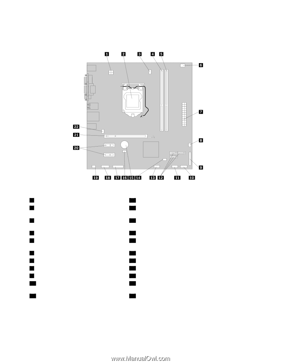
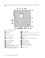
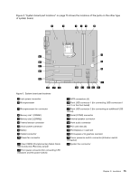
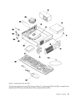
Figure 4 "System board part locations" on page 74 shows the locations of the parts on one type of system board. Figure 4. System board part locations 1 4-pin power connector 2 Microprocessor 3 Microprocessor fan connector 4 Memory slot 1 (DIMM1) 5 Memory slot 2 (DIMM2) 6 Thermal sensor connector 7 24-pin power connector 8 Power fan connector 9 Parallel connector 10 Front panel connector (for connecting LED indicators and the power switch) 11 Front USB connector 1 (for connecting USB connectors 1 and 2 on the front bezel) 12 SATA connectors (3) 13 Front USB connector 2 (for connecting an additional USB device) 14 Clear CMOS (Complementary Metal Oxide Semiconductor) /Recovery jumper 15 Battery 16 Cover presence switch connector (Intrusion switch connector) 17 Serial (COM2) connector 18 Front audio connector 19 Internal speaker connector 20 PCI Express x1 card slots (2) 21 PCI Express x16 graphics card slot 22 System fan connector 74 ThinkCentre Hardware Maintenance Manual
-
 1
1 -
2
-
3
-
4
-
5
-
6
-
7
-
8
-
9
-
10
-
11
-
12
-
13
-
14
-
15
-
16
-
17
-
18
-
19
-
20
-
21
-
22
-
23
-
24
-
25
-
26
-
27
-
28
-
29
-
30
-
31
-
32
-
33
-
34
-
35
-
36
-
37
-
38
-
39
-
40
-
41
-
42
-
43
-
44
-
45
-
46
-
47
-
48
-
49
-
50
-
51
-
52
-
53
-
54
-
55
-
56
-
57
-
58
-
59
-
60
-
61
-
62
-
63
-
64
-
65
-
66
-
67
-
68
-
69
-
70
-
71
-
72
-
 73
73 -
 74
74 -
 75
75 -
 76
76 -
 77
77 -
 78
78 -
 79
79 -
 80
80 -
 81
81 -
 82
82 -
 83
83 -
84
-
85
-
86
-
87
-
88
-
89
-
90
-
91
-
92
-
93
-
94
-
95
-
96
-
97
-
98
-
99
-
100
-
101
-
102
-
103
-
104
-
105
-
106
-
107
-
108
-
109
-
110
-
111
-
112
-
113
-
114
-
115
-
116
-
117
-
118
-
119
-
120
-
121
-
122
-
123
-
124
-
125
-
126
-
127
-
128
-
129
-
130
-
131
-
132
-
133
-
134
-
135
-
136
-
137
-
138
-
139
-
140
-
141
-
142
-
143
-
144
-
145
-
146
-
147
-
148
-
149
-
150
-
151
-
152
-
153
-
154
-
155
-
156
-
157
-
158
-
159
-
160
-
161
-
162
-
163
-
164
-
165
-
166
-
167
-
168
-
169
-
170
 |
 |