Lenovo ThinkPad 560 TP 560Z Technical Reference Manual - Page 38
Real-Time Clock Bytes (X' 000' –X' 00D' ):, Bit 7, Bits 6-4, ThinkPad 560Z System Board - bios setup
 |
View all Lenovo ThinkPad 560 manuals
Add to My Manuals
Save this manual to your list of manuals |
Page 38 highlights
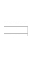
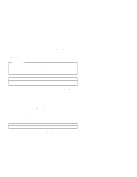
Real-Time Clock Bytes (X'000'-X'00D'): Bit definitions and addresses for the real-time clock bytes are shown in Figure 2-15. Address (Hex) 000 001 002 003 004 005 006 007 008 009 00A 00B 00C 00D Function Seconds Second alarm Minutes Minute alarm Hours Hour alarm Day of week Date of month Month Year Status register A Status register B Status register C Status register D Byte Number 0 1 2 3 4 5 6 7 8 9 10 11 12 13 Figure 2-15. Real-Time Clock Bytes (X'000'-X'00D') Note: The setup program initializes status registers A and B when the time and date are set. Interrupt 1AH is the BIOS interface to read and set the time and date; it initializes the registers in the same way that the setup program does. Status Register A (X'00A') Bit Function 7 Update in progress 6-4 22-stage divider 3-0 Rate-selection bits Figure 2-16. Status Register A (X'00A') Bit 7 Bits 6-4 Bits 3-0 If set to 1, this bit indicates that the time-update cycle is in progress. If set to 0, it indicates that the current date and time can be read. These bits identify which time-base frequency is being used. The system initializes these bits to B'010', which selects a 32.768-kHz time base. This is the only value supported by the system for proper timekeeping. These bits allow the selection of a divider output frequency. The system initializes the rate-selection bits to B'0110', which selects a 1.024-kHz square-wave 2-20 ThinkPad 560Z System Board
-
 1
1 -
2
-
3
-
4
-
5
-
6
-
7
-
8
-
9
-
10
-
11
-
12
-
13
-
14
-
15
-
16
-
17
-
18
-
19
-
20
-
21
-
22
-
23
-
24
-
25
-
26
-
27
-
28
-
29
-
30
-
31
-
32
-
 33
33 -
 34
34 -
 35
35 -
 36
36 -
 37
37 -
 38
38 -
 39
39 -
 40
40 -
 41
41 -
 42
42 -
 43
43 -
44
-
45
-
46
-
47
-
48
-
49
-
50
-
51
-
52
-
53
-
54
-
55
-
56
-
57
-
58
-
59
-
60
-
61
-
62
-
63
-
64
-
65
-
66
-
67
-
68
-
69
-
70
-
71
-
72
-
73
-
74
-
75
-
76
-
77
-
78
-
79
-
80
-
81
-
82
-
83
-
84
-
85
-
86
-
87
-
88
-
89
-
90
-
91
-
92
-
93
-
94
-
95
-
96
-
97
-
98
-
99
-
100
-
101
-
102
-
103
-
104
-
105
-
106
-
107
-
108
-
109
-
110
-
111
-
112
-
113
-
114
-
115
-
116
-
117
-
118
-
119
-
120
-
121
-
122
-
123
-
124
-
125
-
126
-
127
-
128
-
129
-
130
-
131
-
132
-
133
-
134
 |
 |