Lenovo ThinkPad R50 Hardware Maintenance Manual (HMM) - Page 116
System, board, interposer, cover
 |
View all Lenovo ThinkPad R50 manuals
Add to My Manuals
Save this manual to your list of manuals |
Page 116 highlights
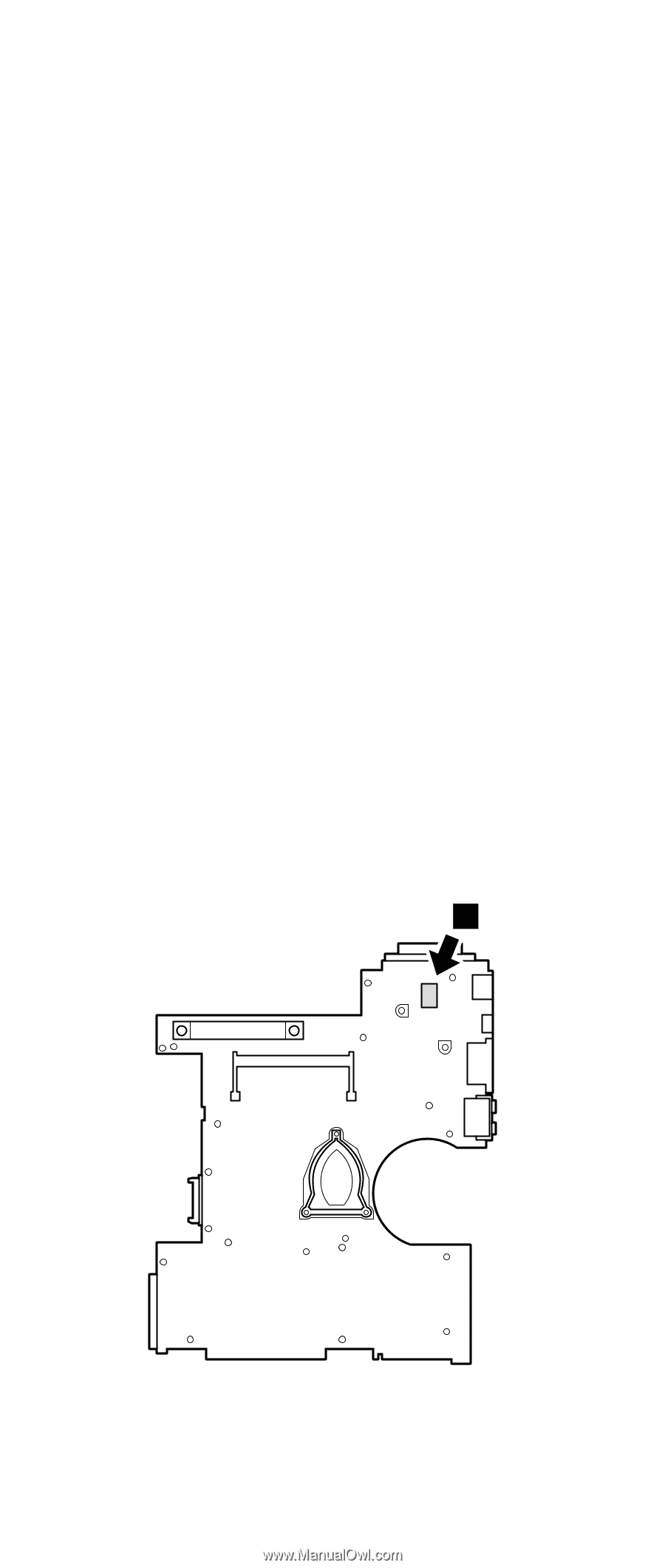
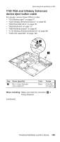
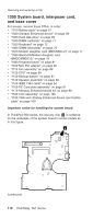
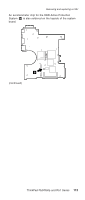
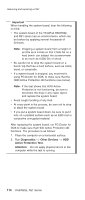
Removing and replacing a FRU 1200 System board, interposer card, and base cover For access, remove these FRUs, in order: v "1010 Battery pack" on page 67 v "1020 Ultrabay Enhanced device" on page 68 v "1030 Hard disk drive" on page 69 v "1040 DIMM (optional)" on page 71 v "1050 Keyboard" on page 72 v "1060 DIMM (standard)" on page 76 v "1070 Modem daughter card (MDC/MDC-2)" on page 77 v "1080 Bluetooth/Modem daughter card (BMDC/BMDC-2)" on page 79 v "1090 Keyboard bezel" on page 81 v "1100 Mini PCI adapter" on page 85 v "1110 Fan assembly" on page 89 v "1120 CPU" on page 90 v "1130 Backup battery" on page 91 v "1140 Speaker assembly" on page 92 v "1150 IEEE 1394 cable" on page 94 v "1160 PC Card slots assembly" on page 97 v "1170 Ultrabay Enhanced shield kit" on page 98 v "1180 LCD assembly" on page 105 v "1190 VGA and Ultrabay Enhanced device eject button cable" on page 109 Important notice for handling the system board: In ThinkPad R50 series, the security chip a is soldered on the underside of the system board in some models as in this figure. a (continued) 112 R50/R50p, R51 Series
-
 1
1 -
2
-
3
-
4
-
5
-
6
-
7
-
8
-
9
-
10
-
11
-
12
-
13
-
14
-
15
-
16
-
17
-
18
-
19
-
20
-
21
-
22
-
23
-
24
-
25
-
26
-
27
-
28
-
29
-
30
-
31
-
32
-
33
-
34
-
35
-
36
-
37
-
38
-
39
-
40
-
41
-
42
-
43
-
44
-
45
-
46
-
47
-
48
-
49
-
50
-
51
-
52
-
53
-
54
-
55
-
56
-
57
-
58
-
59
-
60
-
61
-
62
-
63
-
64
-
65
-
66
-
67
-
68
-
69
-
70
-
71
-
72
-
73
-
74
-
75
-
76
-
77
-
78
-
79
-
80
-
81
-
82
-
83
-
84
-
85
-
86
-
87
-
88
-
89
-
90
-
91
-
92
-
93
-
94
-
95
-
96
-
97
-
98
-
99
-
100
-
101
-
102
-
103
-
104
-
105
-
106
-
107
-
108
-
109
-
110
-
 111
111 -
 112
112 -
 113
113 -
 114
114 -
 115
115 -
 116
116 -
 117
117 -
 118
118 -
 119
119 -
 120
120 -
 121
121 -
122
-
123
-
124
-
125
-
126
-
127
-
128
-
129
-
130
-
131
-
132
-
133
-
134
-
135
-
136
-
137
-
138
-
139
-
140
-
141
-
142
-
143
-
144
-
145
-
146
-
147
-
148
-
149
-
150
-
151
-
152
-
153
-
154
-
155
-
156
-
157
-
158
-
159
-
160
-
161
-
162
-
163
-
164
-
165
-
166
-
167
-
168
-
169
-
170
-
171
-
172
-
173
-
174
-
175
-
176
-
177
-
178
-
179
-
180
-
181
-
182
-
183
-
184
-
185
-
186
-
187
-
188
-
189
-
190
-
191
-
192
-
193
-
194
-
195
-
196
-
197
-
198
-
199
-
200
-
201
-
202
-
203
-
204
-
205
-
206
-
207
-
208
-
209
-
210
-
211
-
212
-
213
-
214
-
215
-
216
-
217
-
218
-
219
-
220
-
221
-
222
-
223
-
224
-
225
-
226
-
227
-
228
-
229
-
230
-
231
-
232
 |
 |