Lenovo ThinkPad T430u Hardware Maintenance Manual - ThinkPad T430u - Page 88
DC-in sub card and base cover assembly, Platform Controller Hub PCH
 |
View all Lenovo ThinkPad T430u manuals
Add to My Manuals
Save this manual to your list of manuals |
Page 88 highlights
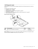
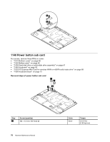
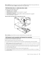
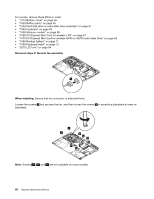
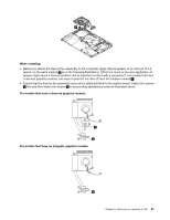
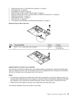
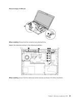
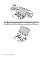
Removal steps of system board Attention: The following components soldered on the system board are extremely sensitive. When you service the system board, avoid any kind of rough handling. a Graphic Processing Unit (GPU) b Microprocessor c Platform Controller Hub (PCH) Note: The GPU is only available for models that have a discrete graphics card. b a c Detach the DC-in sub card connector 1 , and then remove the screws 2 . 2 2 2 2 2 3 2 1 Step 2 Screw (quantity) M2 × 2.0 mm, flat-head (6) Color Bronze When installing: Ensure that the connector is attached firmly. 1170 DC-in sub card and base cover assembly For access, remove these FRUs in order: • "1010 Bottom cover" on page 58 • "1020 Battery pack" on page 60 82 Hardware Maintenance Manual Torque 0.181 Nm (1.85 kgf-cm)
-
 1
1 -
2
-
3
-
4
-
5
-
6
-
7
-
8
-
9
-
10
-
11
-
12
-
13
-
14
-
15
-
16
-
17
-
18
-
19
-
20
-
21
-
22
-
23
-
24
-
25
-
26
-
27
-
28
-
29
-
30
-
31
-
32
-
33
-
34
-
35
-
36
-
37
-
38
-
39
-
40
-
41
-
42
-
43
-
44
-
45
-
46
-
47
-
48
-
49
-
50
-
51
-
52
-
53
-
54
-
55
-
56
-
57
-
58
-
59
-
60
-
61
-
62
-
63
-
64
-
65
-
66
-
67
-
68
-
69
-
70
-
71
-
72
-
73
-
74
-
75
-
76
-
77
-
78
-
79
-
80
-
81
-
82
-
 83
83 -
 84
84 -
 85
85 -
 86
86 -
 87
87 -
 88
88 -
 89
89 -
 90
90 -
 91
91 -
 92
92 -
 93
93 -
94
-
95
-
96
-
97
-
98
-
99
-
100
-
101
 |
 |
