Lenovo ThinkPad W530 Hardware Maintenance Manual - Page 90
Removal steps of keyboard bezel assembly, PANTONE Color Calibrator - restore disk
 |
View all Lenovo ThinkPad W530 manuals
Add to My Manuals
Save this manual to your list of manuals |
Page 90 highlights
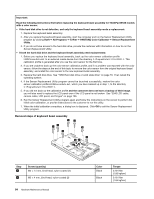
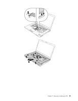
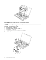
Important: Read the following instructions first before replacing the keyboard bezel assembly for ThinkPad W530 models with a color sensor. • If the hard disk drive is not defective, and only the keyboard bezel assembly needs a replacement: 1. Replace the keyboard bezel assembly. 2. After you replace the keyboard bezel assembly, start the computer and run the Sensor Replacement Utility program by clicking Start ➙ All Programs ➙ X-Rite ➙ PANTONE Color Calibrator ➙ Sensor Replacement Utility. 3. If you do not have access to the hard disk drive, provide the customer with information on how to run the Sensor Replacement Utility. • If both the hard disk drive and the keyboard bezel assembly need replacements: 1. Before you replace the keyboard bezel assembly, back up the color sensor calibration profile ECCM2SensorData.dat to an external media device from the directory C:\ProgramData\X-Rite\ECCM-2. This calibration profile is generated after you use the color sensor for the first time. 2. If you are unable to back up the color sensor calibration profile, and if no problem was reported with the color sensor, follow the steps at the end of this topic to remove the color sensor from the original keyboard bezel assembly, and install the color sensor to the new keyboard bezel assembly. 3. Replace the hard disk drive. See "1050 Hard disk drive or solid state drive" on page 70. Then reload the operating system. 4. If the Sensor Replacement Utility program cannot be launched successfully, restore the color sensor calibration profile ECCM2SensorData.dat, which you have backed up in step 1, to the directory C:\ProgramData\X-Rite\ECCM-2. 5. If you did not back up the calibration profile and the customer does not have a backup of their image, you will also need to replace the LCD panel even if the LCD panel is not broken. See "2040 LCD cable, camera cable, LCD panel, and hinges" on page 106. 6. Run the Sensor Replacement Utility program again and follow the instructions on the screen to perform the initial color calibration, or provide instructions to the customer to run this utility. 7. When the initial calibration completes, a dialog box is displayed. Click OK to exit the Sensor Replacement Utility program. Removal steps of keyboard bezel assembly 1 1 1 1 1 2 1 21 Step 1 2 Screw (quantity) M2 × 14 mm, bind-head, nylon-coated (7) M2 × 4 mm, bind-head, nylon-coated (2) 84 Hardware Maintenance Manual Color Black Black Torque 0.181 Nm (1.85 kgfcm) 0.181 Nm (1.85 kgfcm)
-
 1
1 -
2
-
3
-
4
-
5
-
6
-
7
-
8
-
9
-
10
-
11
-
12
-
13
-
14
-
15
-
16
-
17
-
18
-
19
-
20
-
21
-
22
-
23
-
24
-
25
-
26
-
27
-
28
-
29
-
30
-
31
-
32
-
33
-
34
-
35
-
36
-
37
-
38
-
39
-
40
-
41
-
42
-
43
-
44
-
45
-
46
-
47
-
48
-
49
-
50
-
51
-
52
-
53
-
54
-
55
-
56
-
57
-
58
-
59
-
60
-
61
-
62
-
63
-
64
-
65
-
66
-
67
-
68
-
69
-
70
-
71
-
72
-
73
-
74
-
75
-
76
-
77
-
78
-
79
-
80
-
81
-
82
-
83
-
84
-
 85
85 -
 86
86 -
 87
87 -
 88
88 -
 89
89 -
 90
90 -
 91
91 -
 92
92 -
 93
93 -
 94
94 -
 95
95 -
96
-
97
-
98
-
99
-
100
-
101
-
102
-
103
-
104
-
105
-
106
-
107
-
108
-
109
-
110
-
111
-
112
-
113
-
114
-
115
-
116
-
117
-
118
-
119
-
120
-
121
-
122
 |
 |
