Lenovo ThinkPad W700ds Hardware Maintenance Manual - Page 154
Table 57. Removal steps of second LCD hinges and second LCD rear cover second LCD cover kit for ThinkPad, W700ds and W701ds continued
 |
View all Lenovo ThinkPad W700ds manuals
Add to My Manuals
Save this manual to your list of manuals |
Page 154 highlights
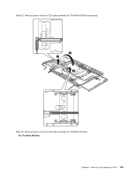
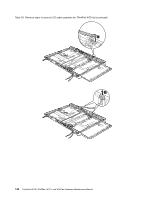
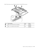
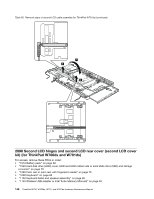
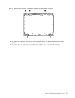
Table 57. Removal steps of second LCD hinges and second LCD rear cover (second LCD cover kit) (for ThinkPad W700ds and W701ds) (continued) 2 3 4 3 4 Step 3 Screw (quantity) M2.5 × 3.5 mm, wafer-head, nylon-coated (2) Color Black Torque 0.392 Nm (4 kgfcm) When installing: After replacing the hinges or the second LCD rear cover and reinstalling the second LCD cable and the second LCD panel, press the second LCD unit into the main LCD rear cover a . Then make sure that the right side of the second LCD unit is aligned to the right edge of the main LCD cover as shown in b in this figure. To adjust the alignment, adjust the fastening of screws c . 148 ThinkPad W700, W700ds, W701, and W701ds Hardware Maintenance Manual
-
 1
1 -
2
-
3
-
4
-
5
-
6
-
7
-
8
-
9
-
10
-
11
-
12
-
13
-
14
-
15
-
16
-
17
-
18
-
19
-
20
-
21
-
22
-
23
-
24
-
25
-
26
-
27
-
28
-
29
-
30
-
31
-
32
-
33
-
34
-
35
-
36
-
37
-
38
-
39
-
40
-
41
-
42
-
43
-
44
-
45
-
46
-
47
-
48
-
49
-
50
-
51
-
52
-
53
-
54
-
55
-
56
-
57
-
58
-
59
-
60
-
61
-
62
-
63
-
64
-
65
-
66
-
67
-
68
-
69
-
70
-
71
-
72
-
73
-
74
-
75
-
76
-
77
-
78
-
79
-
80
-
81
-
82
-
83
-
84
-
85
-
86
-
87
-
88
-
89
-
90
-
91
-
92
-
93
-
94
-
95
-
96
-
97
-
98
-
99
-
100
-
101
-
102
-
103
-
104
-
105
-
106
-
107
-
108
-
109
-
110
-
111
-
112
-
113
-
114
-
115
-
116
-
117
-
118
-
119
-
120
-
121
-
122
-
123
-
124
-
125
-
126
-
127
-
128
-
129
-
130
-
131
-
132
-
133
-
134
-
135
-
136
-
137
-
138
-
139
-
140
-
141
-
142
-
143
-
144
-
145
-
146
-
147
-
148
-
 149
149 -
 150
150 -
 151
151 -
 152
152 -
 153
153 -
 154
154 -
 155
155 -
 156
156 -
 157
157 -
 158
158 -
 159
159 -
160
-
161
-
162
-
163
-
164
-
165
-
166
-
167
-
168
-
169
-
170
-
171
-
172
-
173
-
174
-
175
-
176
-
177
-
178
-
179
-
180
-
181
-
182
-
183
-
184
-
185
-
186
-
187
-
188
-
189
-
190
-
191
-
192
-
193
-
194
-
195
-
196
-
197
-
198
-
199
-
200
-
201
-
202
-
203
-
204
-
205
-
206
-
207
-
208
-
209
-
210
-
211
-
212
-
213
-
214
-
215
-
216
-
217
-
218
 |
 |
Table 57. Removal steps of second LCD hinges and second LCD rear cover (second LCD cover kit) (for ThinkPad
W700ds and W701ds) (continued)
2
3
4
4
3
Step
Screw (quantity)
Color
Torque
3
M2.5 × 3.5 mm, wafer-head, nylon-coated (2)
Black
0.392 Nm
(4 kgfcm)
When installing:
After replacing the hinges or the second LCD rear cover and reinstalling the second LCD cable and
the second LCD panel, press the second LCD unit into the main LCD rear cover
a
. Then make sure that the right
side of the second LCD unit is aligned to the right edge of the main LCD cover as shown in
b
in this figure. To
adjust the alignment, adjust the fastening of screws
c
.
148
ThinkPad W700, W700ds, W701, and W701ds Hardware Maintenance Manual