Lenovo ThinkPad i Series 1157 ThinkPad 570 UltraBase User's Guide - Page 6
Identifying the hardware features, Front view
 |
View all Lenovo ThinkPad i Series 1157 manuals
Add to My Manuals
Save this manual to your list of manuals |
Page 6 highlights
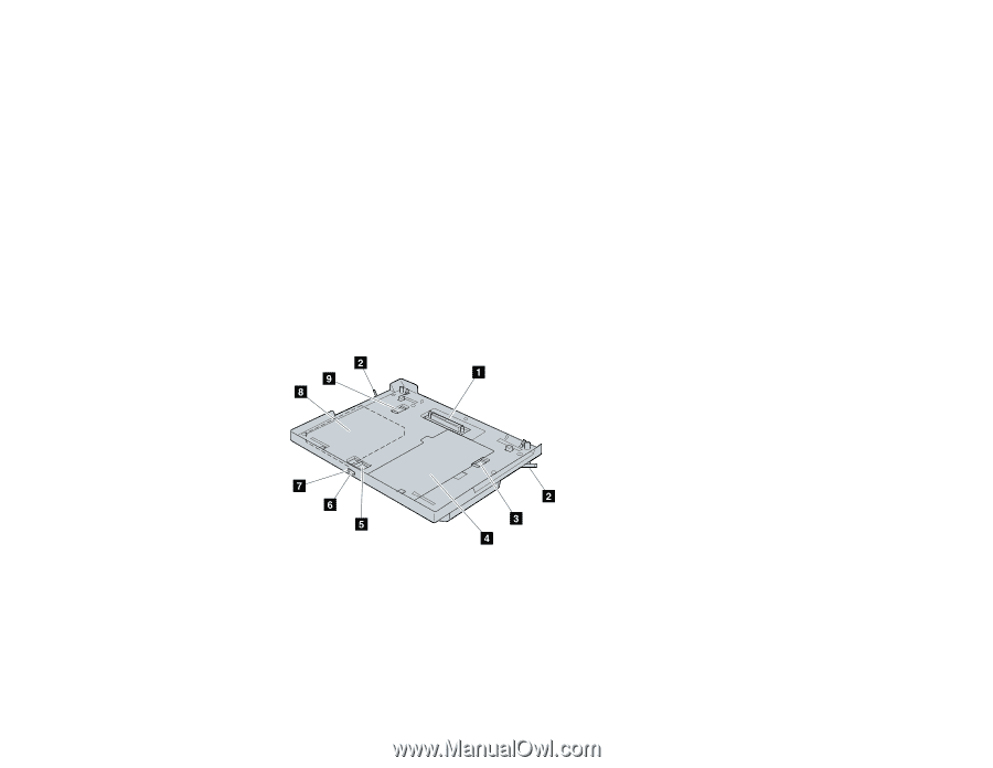
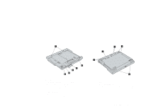
Identifying the hardware features Front view 1 The docking connector is where you attach your ThinkPad computer to the UltraBase. 2 You release these eject levers when you remove the computer. 3 The bay lock prevents the device in the diskette-drive/battery bay from being removed. 4 The diskette-drive/battery bay is used for installing a secondary battery pack or a diskette drive. 5 The bay eject lever ejects the device in the bays. 6 With the eject request button, you can request to remove the device in the bays. 7 The status indicator indicates when you can safely remove a device in the bays. 8 The UltraslimBay is used for installing various devices such as a CD-ROM drive, a DVD drive, an LS-120, and a secondary hard disk drive. 9 The UltraslimBay lock prevents the device in the UltraslimBay from being removed. 1-2
-
 1
1 -
 2
2 -
 3
3 -
 4
4 -
 5
5 -
 6
6 -
 7
7 -
 8
8 -
 9
9 -
 10
10 -
 11
11 -
 12
12 -
13
-
14
-
15
-
16
-
17
-
18
-
19
-
20
-
21
-
22
-
23
-
24
-
25
-
26
-
27
 |
 |