Lenovo U31-70 Laptop Hardware Maintenance Manual - Lenovo U31-70 - Page 62
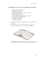
Removal steps of integrated camera, antenna assembly and LCD, hinges continued
 |
View all Lenovo U31-70 Laptop manuals
Add to My Manuals
Save this manual to your list of manuals |
Page 62 highlights
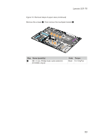
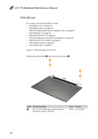
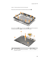
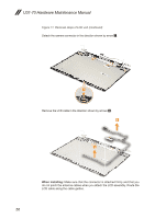
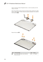
U31-70 Hardware Maintenance Manual Figure 12. Removal steps of integrated camera, antenna assembly and LCD hinges (continued) Peel off the adhesive tape securing the antenna boards, release the cables from the cable guide, and then remove the antenna assembly in the direction shown by arrows 2. 2 2 Remove the screws 3. 3 33 3 33 Step Screw (quantity) 3 M2 × 6 mm, Phillips-head, nylok-coated (6) lcd brk---lcd cover Color Torque Black 1.0~1.5 kgf*cm 58
-
 1
1 -
2
-
3
-
4
-
5
-
6
-
7
-
8
-
9
-
10
-
11
-
12
-
13
-
14
-
15
-
16
-
17
-
18
-
19
-
20
-
21
-
22
-
23
-
24
-
25
-
26
-
27
-
28
-
29
-
30
-
31
-
32
-
33
-
34
-
35
-
36
-
37
-
38
-
39
-
40
-
41
-
42
-
43
-
44
-
45
-
46
-
47
-
48
-
49
-
50
-
51
-
52
-
53
-
54
-
55
-
56
-
 57
57 -
 58
58 -
 59
59 -
 60
60 -
 61
61 -
 62
62 -
 63
63 -
 64
64 -
 65
65 -
 66
66 -
 67
67 -
68
-
69
-
70
-
71
-
72
-
73
-
74
-
75
-
76
-
77
-
78
-
79
-
80
 |
 |

58
U31-70 Hardware Maintenance Manual
Figure 12. Removal steps of integrated camera,
antenna assembly and LCD
hinges (continued)
Peel off the adhesive tape securing the antenna boards, release the cables
from the cable guide, and then remove the antenna assembly in the direction
shown by arrows
2
.
2
2
Remove the screws
3
.
3
3
3
3
3
3
Step
Screw (quantity)
Color
Torque
3
M2 × 6 mm, Phillips-head, nylok-coated (6)
lcd brk---lcd cover
Black
1.0~1.5 kgf*cm