Lenovo U410 Touch Laptop Hardware Maintenance Manual - IdeaPad U310, U410, U31 - Page 42
U410/U410 Touch, the machine.
 |
View all Lenovo U410 Touch Laptop manuals
Add to My Manuals
Save this manual to your list of manuals |
Page 42 highlights
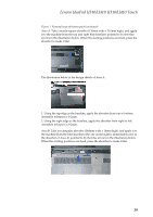
Lenovo IdeaPad U310/U410 U310/U410 Touch Hardware Maintenance Manual Figure 1. Removal steps of battery pack (continued) After affixing the absorbers, use the illustration below to check to ensure that all absorbers are in the right locations. Then press the absorbers, until they are flat and there are no bubbles, no curled edges. After affixing absorbers and changing Wireless LAN card, re-assemble the device. First connect the battery interface. Then replace the bottom cover over the absorber materials, reassembling with care. Note: 1. Connect antenna to the wireless network card correctly: port M should be connected to the black antenna, and port A should be connected to the white antenna. 2. The assembling process requires gentle handling to avoid bottom cover deformation. If the network card has been replaced, when you've finished the assembling, log into the operating system and remove the old wireless network card driver and bluetooth driver from the Control Panel manually. Then reinstall the wireless network card and bluetooth driver. Note: The old bluetooth driver has to be removed manually before installing a new one. Otherwise, the bluetooth driver may not function. When the steps above have been completed, follow the normal procedures to test the machine. U410/U410 Touch After removing the bottom cover, turn over the console and lay it flat on the work space. As shown in the illustration below, absorbers (Part No. XXXXXX) will be attached onto four red areas: A, B , C and D. Apply black Mylar (Part No.YYYYYY ) to the yellow area in Area C. Use the corresponding size of absorber, and apply it to the machine from the blue baselines pointed to by the blue arrows in the illustration below. When the starting positions are fixed, press the absorber to make it flat. Affix them in the areas of A, B , C and D in order. 38
-
 1
1 -
2
-
3
-
4
-
5
-
6
-
7
-
8
-
9
-
10
-
11
-
12
-
13
-
14
-
15
-
16
-
17
-
18
-
19
-
20
-
21
-
22
-
23
-
24
-
25
-
26
-
27
-
28
-
29
-
30
-
31
-
32
-
33
-
34
-
35
-
36
-
 37
37 -
 38
38 -
 39
39 -
 40
40 -
 41
41 -
 42
42 -
 43
43 -
 44
44 -
 45
45 -
 46
46 -
 47
47 -
48
-
49
-
50
-
51
-
52
-
53
-
54
-
55
-
56
-
57
-
58
-
59
-
60
-
61
-
62
-
63
-
64
-
65
-
66
-
67
-
68
-
69
-
70
-
71
-
72
-
73
-
74
-
75
-
76
-
77
-
78
-
79
-
80
-
81
-
82
-
83
-
84
-
85
-
86
-
87
-
88
-
89
-
90
-
91
-
92
-
93
-
94
-
95
-
96
-
97
-
98
-
99
-
100
-
101
-
102
-
103
-
104
-
105
-
106
-
107
-
108
-
109
-
110
-
111
-
112
-
113
-
114
-
115
 |
 |
