Lenovo U410 Touch Laptop Hardware Maintenance Manual - IdeaPad U310, U410, U31 - Page 43
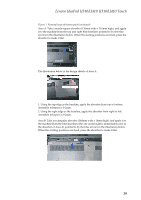
Area B: Take a rectangular absorber 148mm wide x 14mm high, and apply it
 |
View all Lenovo U410 Touch Laptop manuals
Add to My Manuals
Save this manual to your list of manuals |
Page 43 highlights
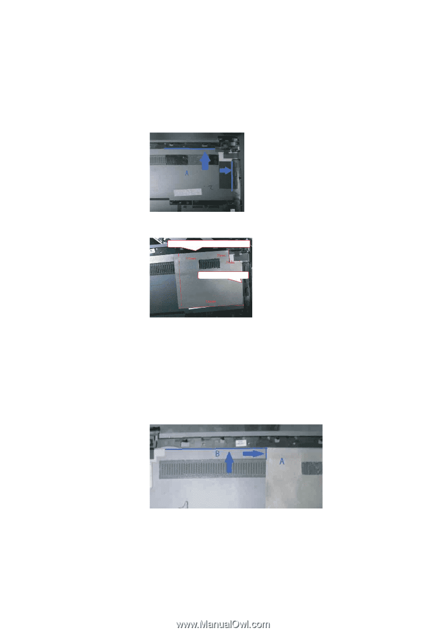
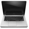
Lenovo IdeaPad U310/U410 U310/U410 Touch Figure 1. Removal steps of battery pack (continued) Area A: Take a nearly-square absorber (130mm wide x 110mm high), and apply it to the machine from the top and right blue baselines pointed to by the blue arrows in the illustration below. When the starting positions are fixed, press the absorber to make it flat. The illustration below is the design sketch of Area A. 1 2 1: Using the top edge as the baseline, apply the absorber from top to bottom. Assembly tolerance is 0-2mm. 2: Using the right edge as the baseline, apply the absorber from right to left. Assembly tolerance is 0-2mm. Area B: Take a rectangular absorber (148mm wide x 14mm high), and apply it to the machine from the blue baselines (the one on the right is immediately next to the absorber of Area A) pointed to by the blue arrows in the illustration below. When the starting positions are fixed, press the absorber to make it flat. 39
-
 1
1 -
2
-
3
-
4
-
5
-
6
-
7
-
8
-
9
-
10
-
11
-
12
-
13
-
14
-
15
-
16
-
17
-
18
-
19
-
20
-
21
-
22
-
23
-
24
-
25
-
26
-
27
-
28
-
29
-
30
-
31
-
32
-
33
-
34
-
35
-
36
-
37
-
 38
38 -
 39
39 -
 40
40 -
 41
41 -
 42
42 -
 43
43 -
 44
44 -
 45
45 -
 46
46 -
 47
47 -
 48
48 -
49
-
50
-
51
-
52
-
53
-
54
-
55
-
56
-
57
-
58
-
59
-
60
-
61
-
62
-
63
-
64
-
65
-
66
-
67
-
68
-
69
-
70
-
71
-
72
-
73
-
74
-
75
-
76
-
77
-
78
-
79
-
80
-
81
-
82
-
83
-
84
-
85
-
86
-
87
-
88
-
89
-
90
-
91
-
92
-
93
-
94
-
95
-
96
-
97
-
98
-
99
-
100
-
101
-
102
-
103
-
104
-
105
-
106
-
107
-
108
-
109
-
110
-
111
-
112
-
113
-
114
-
115
 |
 |