Lenovo Y410P Laptop Hardware Maintenance Manual - IdeaPad Y410p, Y510p - Page 71
LCD unit
 |
View all Lenovo Y410P Laptop manuals
Add to My Manuals
Save this manual to your list of manuals |
Page 71 highlights
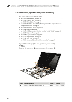
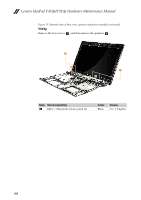
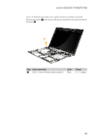
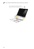
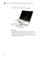
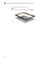
Lenovo IdeaPad Y410p/Y510p 1140 LCD unit For access, remove these FRUs in order: • see "1010 Battery pack" on page 34 • see "1020 Dummy card" on page 35 • see "1030 Optical drive" on page 36 • see "1040 Hard disk drive(HDD)/Memory/Mini PCI Express Card slot compartment cover" on page 37 • see "1050 Hard disk drive" on page 39 • see "1060 DIMM" on page 41 • see "1070 PCI Express Mini Card for wireless LAN/WAN" on page 42 • see "1080 Keyboard" on page 44 • see "1090 Keyboard bezel" on page 48 • see "1100 System board" on page 55 • see "1130 Base cover, speakers and power assembly" on page 62 Figure 14. Removal steps of LCD unit Y410p Release the antenna cables from the cable guides in the direction shown by arrows a . Remove screws b . 2 2 2 1 2 1 1 Step Screw (quantity) b M2.5 × 4 mm flat-head, nylok-coated (4) Color Torque Black 1.5 ~2.0 kgfcm 67
-
 1
1 -
2
-
3
-
4
-
5
-
6
-
7
-
8
-
9
-
10
-
11
-
12
-
13
-
14
-
15
-
16
-
17
-
18
-
19
-
20
-
21
-
22
-
23
-
24
-
25
-
26
-
27
-
28
-
29
-
30
-
31
-
32
-
33
-
34
-
35
-
36
-
37
-
38
-
39
-
40
-
41
-
42
-
43
-
44
-
45
-
46
-
47
-
48
-
49
-
50
-
51
-
52
-
53
-
54
-
55
-
56
-
57
-
58
-
59
-
60
-
61
-
62
-
63
-
64
-
65
-
 66
66 -
 67
67 -
 68
68 -
 69
69 -
 70
70 -
 71
71 -
 72
72 -
 73
73 -
 74
74 -
 75
75 -
 76
76 -
77
-
78
-
79
-
80
-
81
-
82
-
83
-
84
-
85
-
86
-
87
-
88
-
89
-
90
-
91
-
92
-
93
-
94
-
95
-
96
-
97
-
98
-
99
-
100
-
101
-
102
-
103
-
104
-
105
-
106
-
107
-
108
-
109
-
110
-
111
-
112
 |
 |